Fundamental Principles and System Description
Engineering Information
SINAMICS Engineering Manual – November 2015
Ó Siemens AG
105/528
The criteria for defining of the required transformer power rating, taking into account the harmonic load as well as the
characteristics of three-winding transformers in 12-pulse operation, are described in the section “Transfomers”.
1.6.3 Active Infeed
The Active Infeed is an actively pulsed, stable, regulated rectifier / regenerative unit for four-quadrant operation, i.e.
the energy flows from the supply system to the DC link and vice versa. The current values stated in the catalogs are
available in both rectifier and regenerative operation
The Active Infeed comprises a self-commutated IGBT inverter (Active Line Module ALM), which operates on the
supply system via the Clean Power Filter (Active Interface Module). The Active Line Module operates according to
the method of pulse-width modulation and generates a constant, regulated DC link voltage V
DCLink
from the three-
phase line voltage V
Line
. The Clean Power Filter, which is installed between the Active Line Module and the supply
system, filters out, as far as possible, the harmonics from the Active Line Module’s pulse-width modulated voltage
V
ALM
, thereby ensuring a virtually sinusoidal input current on the line side and, therefore, minimal harmonic effects on
the supply system.
The Active Infeed is the highest grade SINAMICS Infeed variant. It is an integral component of SINAMICS S150
cabinet units and is available as a stand-alone Infeed of the SINAMICS S120 modular drive system in Chassis or
Cabinet Modules format.
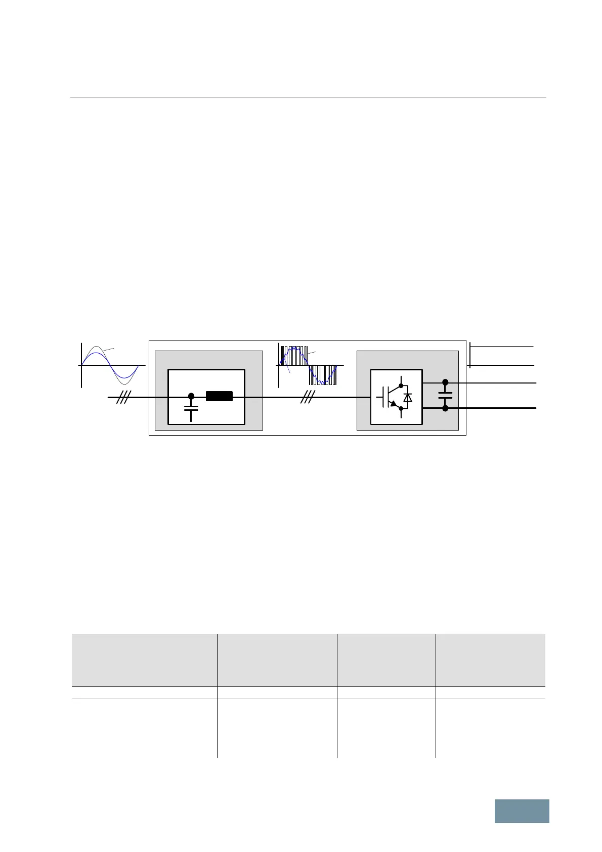
Active Interface Module AIM Active Line Module ALM
Clean Power Filter
Supply
DC Link
V
Line
I
Line
V
ALM
I
ALM
V
DC Link
Active Infeed
SINAMICS S120 Active Infeed comprising an Active Interface Module and an Active Line Module
The Active Infeed is a self-commutated rectifier / regenerative unit and produces from the three-phase line voltage
V
Line
a regulated DC link voltage V
DCLink,
which remains constant independently from line voltage variations and
supply voltage dips. It operates as a step-up converter, i.e. the DC link voltage is always higher than the peak value
of the line voltage (V
DCLink
> 1.41 • V
Line
). The value can be parameterized (1.42 to 2.0) and its factory setting is
V
DCLink
= 1.50 • V
Line
This setting should not be changed without a valid reason. Reducing the factory-set value tends to impair the control
quality while increasing it unnecessarily increases the voltage on the inverter and the motor winding. If the
permissible voltage of the motor winding is sufficiently high (see section "Increased voltage stress on the motor
winding as a result of long cables"), the DC link voltage can be increased from the factory setting to the values
V
DCmax
specified in the table. This method allows a voltage higher than the line voltage to be obtained at the output of
the inverter or Motor Module connected to the Active Infeed. The table shows the maximum achievable inverter
output voltage as a function of the DC link voltage and the modulation system used in vector control mode (space
vector modulation SVM without overmodulation or pulse-edge modulation PEM).
Supply voltage
V
Maximum permissible DC
link voltage in steady-state
operation
V
DC max.
Maximum attainable
output voltage with
space vector
modulation
V
Maximum attainable
output voltage with
pulse-edge modulation
V
out max. PEM
Units with 380 V – 480 V 3AC 720 V 504 V 533 V
Units with 500 V – 690 V 3AC
in operation with supply voltages
500 V – 600 V 3AC
660 V – 690 V 3AC
1000 V with V
Line
= 500 V
1080 V with V
Line
= 600 V
1080 V
700 V with V
Line
= 500 V
756 V with V
Line
= 600 V
756 V
740 V with V
Line
= 500 V
800 V with V
Line
= 600 V
800 V
SINAMICS Active Infeed: Maximum, continuously permissible DC link voltages and attainable output voltages
 Loading...


