Fundamental Principles and System Description
Engineering Information
SINAMICS Engineering Manual – November 2015
Ó Siemens AG
22/528
unit is in operation, by changing a parameter setting or switching to another data set, for example. By altering the
current controller clock cycle, it is also possible to set different pulse frequency values, in other words, the pulse
frequency can be very finely adjusted. However, the current controller clock cycle can be changed only when the
drive is in commissioning mode.
1.1.3.2 Interrelationships between current controller clock cycle, pulse frequency and output
frequency
For SINAMICS G130, G150, S150 and S120 converters and inverters (Chassis and Cabinet Modules formats)
described in this engineering manual and vector-type drive objects (vector and V/f control modes), the following
interdependencies exist between the current controller clock cycle, the pulse frequency and the output frequency:
Dependence of the settable pulse frequency f
Pulse
on the current controller clock cycle setting T
I
:
f
Pulse
= n • (1 / T
I
) where n = ½, 1, 2, 3, … .(applies to vector and V/f control modes) (1)
Dependence of the maximum attainable output frequency f
out max
on the current controller clock cycle setting T
I
:
f
out max
≤ 1 / (8.3333 • T
I
) . (applies only to vector control mode but not to V/f control mode) (2)
Dependence of the maximum attainable output frequency f
out max
on the pulse frequency setting f
Pulse
:
f
out max
≤ f
Pulse
/ 12 . (applies to vector and V/f control modes) (3)
Regardless of the formulas specified above, the maximum possible output frequency f
out max
is limited to 550 Hz in
the standard firmware for the vector and U/f control modes with SINAMICS G and S. With the license "High output
frequency" (6SL3074-0AA02-0AA0) for SINAMICS S (which can also be ordered as option J01 for the SINAMICS S
CompactFlash card), it is now possible to increase the maximum possible output frequency f
out max
to 650 Hz. The
"High output frequency" license is subject to export restrictions. Further information is available on request.
When firmware version 4.3 is used, the minimum settable current controller clock cycle is 250 μs for vector-type drive
objects (vector and V/f control modes) of all SINAMICS G and SINAMICS S Chassis and cabinet units.
When firmware version 4.4 or higher is used, a minimum current controller clock cycle of 125 μs can be set for
vector-type drive objects (vector and V/f control modes) of SINAMICS S Chassis and cabinet units. The only
exceptions are the parallel connections of SINAMICS S converters for which the minimum permissible current
controller clock cycle is 200 μs. For SINAMICS G converters, the minimum permissible current controller clock cycle
setting remains 250 μs and the minimum permissible speed controller clock cycle is also unchanged at 1 ms.
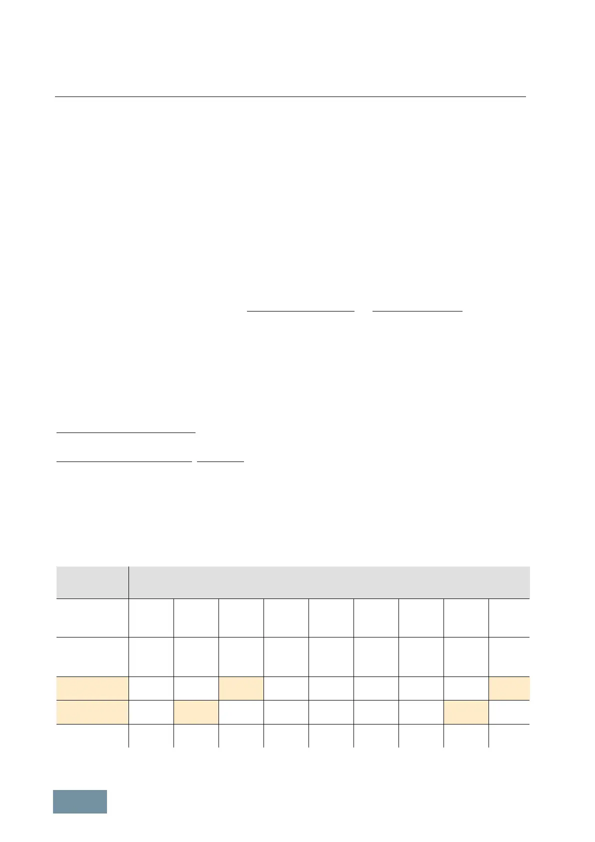
Vector-type drive object with vector control mode
For vector control mode the table below shows the settable pulse frequencies f
Pulse
and the associated maximum
attainable output frequencies f
out max
as a function of the current controller clock cycle setting T
I
in accordance with
equations (1) to (3) (which must all be satisfied simultaneously).
Current
controller
clock cycle
Settable pulse frequencies and associated max. output frequencies (exact, non-rounded values)
125 μs
(FW version 4.4
or higher
for SINAMICS S)
4.00 kHz
333 Hz
8.0 kHz
550 Hz /
650 Hz
1
200 μs
(FW version 4.4
or higher
for SINAMICS S)
2.50 kHz
208 Hz
5.00 kHz
416 Hz
250 μs
2
SINAMICS G + S
2.00 kHz
166 Hz
4.00 kHz
333 Hz
8.0 kHz
480 Hz
400 μs
3
SINAMICS G + S
1.25 kHz
104 Hz
2.50 kHz
208 Hz
5.00 kHz
300 Hz
7.5 kHz
300 Hz
500 μs
SINAMICS G + S
1.00 kHz
83 Hz
2.00 kHz
166 Hz
4.00 kHz
240 Hz
6.00 kHz
240 Hz
8.0 kHz
240 Hz
1
Only with the license "High output frequency" that is available as option J01 for the SINAMICS S CompactFlash card
 Loading...


