SINAMICS S120 Cabinet Modules
Engineering Information
SINAMICS Engineering Manual – November 2015
Ó Siemens AG
433/528
7.2.10 Central Braking Modules
7.2.10.1 Design
Central Braking Modules are placed in a central position within the drive configuration built of S120 Cabinet Modules.
They limit the DC link voltage if regenerative energy is fed back to the DC link in systems which are not capable of
regenerative feedback to the mains supply. They therefore allow fast braking of the drives and avoid fault trips of the
Motor Modules caused by DC link overvoltage.
-
X10
0
-
F24
PE
PE
If the DC busbar voltage exceeds the response threshold in generator operation, the
braking unit integrated in the Cabinet Module is activated and starts to supply energy to the
externally mounted braking resistor. The DC link voltage is thus prevented from increasing
further. The braking resistor converts the energy into heat.
The response time of the Braking Unit in the Central Braking Module is within the 1 to 2 ms
range and the response threshold tolerance within the 1.5 to 3 V range. The possible
response threshold settings and associated switch positions on the Braking Unit can be
found in the table at the bottom of this page.
Central Braking Modules are an alternative to the optional Braking Modules which can be
fitted in the Power Modules in Chassis format by selecting options L61, L62 or L64, L65.
They are of particular advantage in drive configurations which require high braking powers.
Central Braking Modules operate completely autonomously and simply require a
connection to the DC link. An external control voltage is not needed.
Braking units can be operated on power supply systems of any type (TN and IT).
The units have an integrated temperature monitoring. An internal fan provided as a
standard supports the cooling of the power unit. Switching on and off of the fan is
temperature-controlled. Thus continuous operation of the fan is avoided. The permissible
ambient temperature for operation with rated power is 0°C - 40º C. At higher temperatures
between 40ºC and 50ºC a power derating has to be taken into account in accordance with
the formula:
rated
PCTP *°-*-= )](.[ 4002501
The installation altitude can be up to 2000 m above sea level. For altitudes higher than
1000 m, a power derating has to be taken into account, which is 1.5% per 100 m.
In addition to the temperature monitoring function, other protection measures are
implemented such as overcurrent and overload protection.
The braking units are also equipped with LEDs for optical indication of fault conditions and
a control output, which is activated in case of a fault. The braking unit can be externally
blocked using a control input.
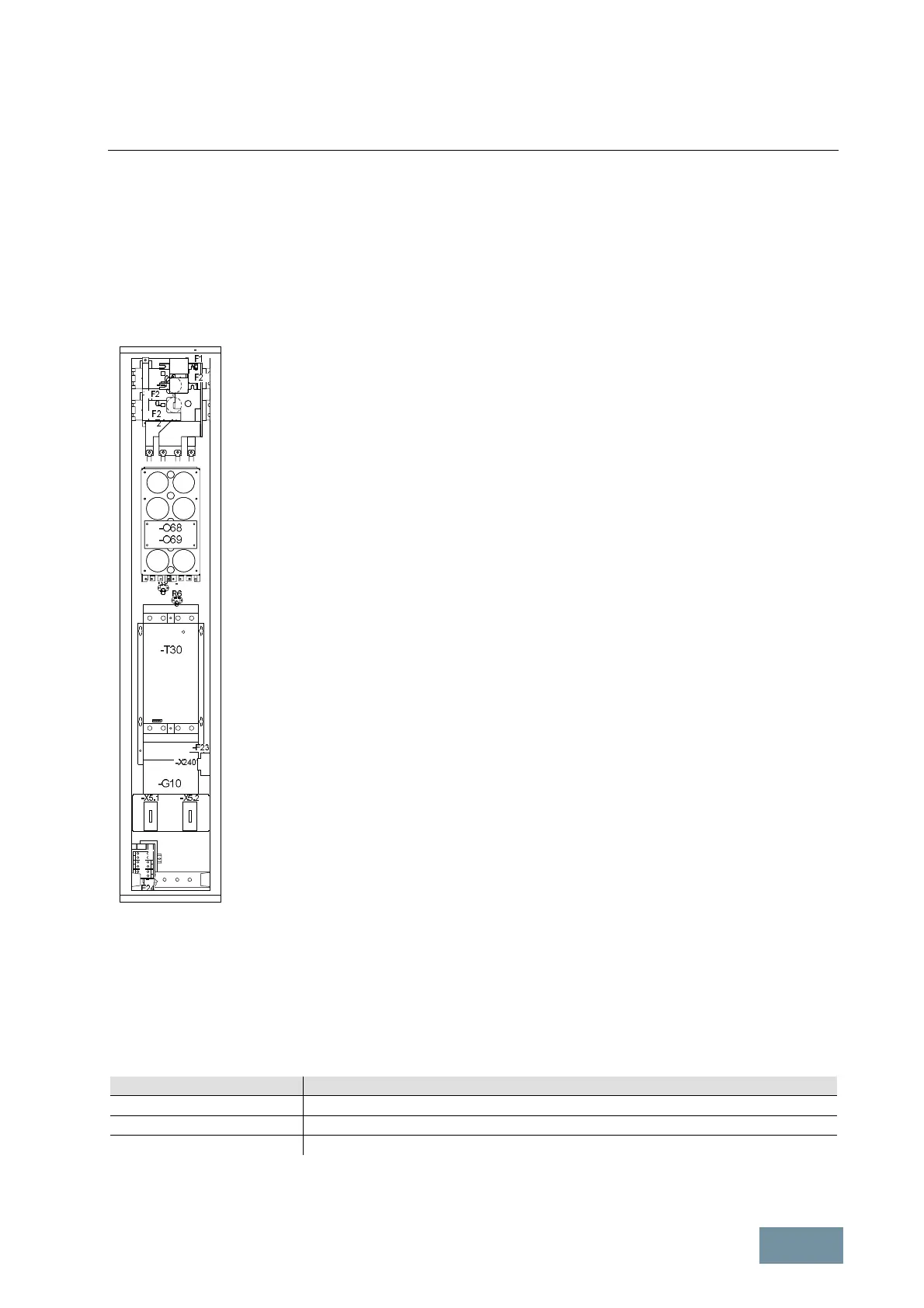
Central Braking Module
To reduce the voltage stress on the motor and converter, the response threshold of the braking unit and thus also the
DC link voltage which is generated during braking can be reduced at lower line voltages of the permissible line
voltage ranges, i.e. at line voltages of 380 V – 400 V or 500 V or 660 V). However, the attainable peak power is then
also reduced with the square of the response threshold ratio.
The factory setting in each case is the upper response threshold as indicated by switch position 1 of switch S2. The
settable response thresholds and associated switch positions (1 or 2) are shown in the table below.
Line supply voltage Response thresholds and associated switch positions of switch S2
380 V – 480 V 3AC 770 V (switch position 1) or 670 V (switch position 2)
500 V – 600 V 3AC 960 V (switch position 1) or 840 V (switch position 2)
660 V – 690 V 3AC 1155 V (switch position 1) or 1065 V (switch position 2)
Response thresholds of the Central Braking Module and associated switch positions of switch S2
 Loading...


