Fundamental Principles and System Description
Engineering Information
SINAMICS Engineering Manual – November 2015
Ó Siemens AG
16/528
1 Fundamental Principles and System Description
1.1 Operating principle of SINAMICS converters
1.1.1 General operating principle
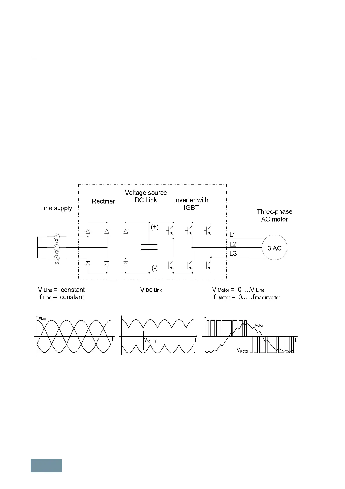
The converters in the SINAMICS product range are PWM converters with a voltage-source DC link. At the input side,
the converter consists of a rectifier (shown in the schematic sketch as a thyristor rectifier) which is supplied with a
constant voltage V
Line
and a constant frequency f
Line
from a three-phase supply. The rectifier produces a constant DC
voltage V
DCLink
, i.e. the DC link voltage, which is smoothed by the DC link capacitors. The 2-level IGBT inverter on
the output side converts the DC link voltage to a three-phase system with a variable voltage V
Motor
and variable
frequency f
Motor
. This process operates according to the principle of pulse-width modulation PWM. By varying the
voltage and the frequency, it is possible to vary the speed of the connected three-phase motor continuously and
virtually without losses.
Block diagram of a PWM converter with voltage-source DC link
1.1.2 Pulse modulation method
The power semiconductors of the IGBT inverter (IGBT = Insulated Gate Bipolar Transistor) are high-speed, electronic
switches which connect the converter outputs to the positive or negative pole of the DC link voltage. The duration of
the gating signals in the individual inverter phases and the magnitude of the DC link voltage thus clearly determine
the output voltage and therefore also the voltage at the connected motor.
 Loading...


