SINAMICS S120 Cabinet Modules
Engineering Information
SINAMICS Engineering Manual – November 2015
Ó Siemens AG
413/528
7.2.4.2 Planning recommendations, special features
Line Modules should be connected as standard on the right of a Line Connection Module. Line Modules can also be
erected to the left of the LCM with frame size KL and LL. However, this rule applies only to Line Modules. Other types
of Cabinet Modules can be connected at any side of a Line Connection Module. It must be noted that option M26
(side panel mounted on the right) cannot be used on an LCM.
Options L42 (LCM for Active Infeed), L43 (LCM for Basic Line Module) and L44 (LCM for Smart Line Module) must
also be taken into account. These serve to assign the LCM to the adjacent Line Modules. They include precharging
circuits and cable connections to the relevant Infeed or Line Module. For this reason, it is advisable to place the LCM
and Line Modules within the same transport unit. In this case, the necessary cable connections will be made in the
factory.
If a grounding switch is also needed, the space it requires means that an LCM in frame size KL or LL must be used.
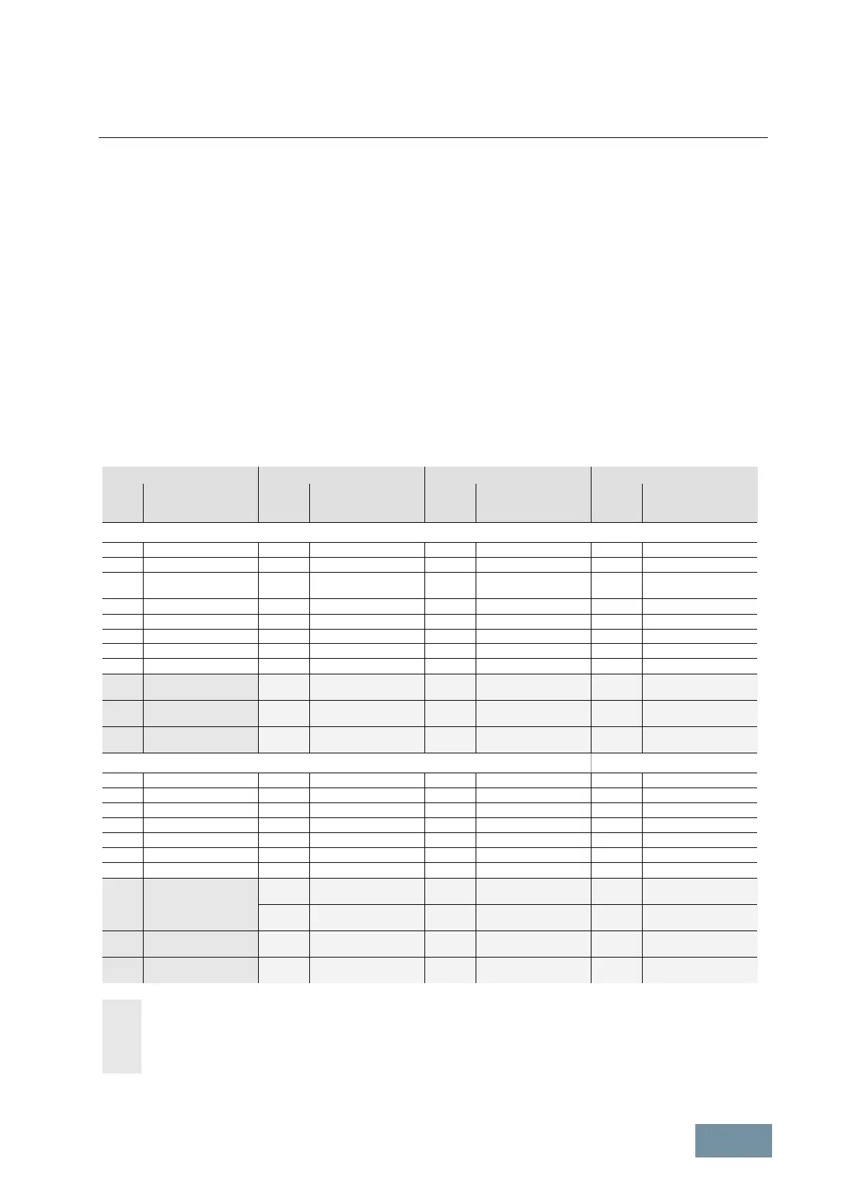
7.2.4.3 Assignment to the rectifiers / Line Modules
To simplify the configuring process, the correct Line Connection Modules are already assigned to the rectifiers (Line
Modules). The table below shows the possible combinations.
Line Connection Modules Basic Line Modules Smart Line Modules Active Line Modules
Current
[AC]
1)
A
Order No. Current.
[AC]
A
Order No. Current.
[AC]
A
Order No. Current.
[AC]
A
Order No.
Supply voltage 380 V - 480 V 3AC
250
6SL3700-0LE32-5AA3
210
6SL3730-7TE32-1BA3
380
6SL3700-0LE34-0AA3
260
6SL3730-7TE32-6BA3
600
6SL3700-0LE36-3AA3
365
460
6SL3730-1TE34-2AA3
6SL3730-1TE35-3AA3
463
6SL3730-6TE35-5AA3
380
490
6SL3730-7TE33-8BA3
6SL3730-7TE35-0BA3
770
6SL3700-0LE38-0AA3
710
6SL3730-1TE38-2AA3
614
6SL3730-6TE37-3AA3
605
6SL3730-7TE36-1BA3
1000
6SL3700-0LE41-0AA3
883
6SL3730-6TE41-1AA3
840
6SL3730-7TE38-4BA3
1250
6SL3700-0LE41-3AA3
1010
6SL3730-1TE41-2AA3
1093
6SL3730-6TE41-3AA3
985
6SL3730-7TE41-0BA3
1600
6SL3700-0LE41-6AA3
1265
6SL3730-1TE41-5AA3
1430
6SL3730-6TE41-7AA3
1405
6SL3730-7TE41-4BA3
2000
6SL3700-0LE42-0AA3
1630
6SL3730-1TE41-8AA3
2000
6SL3700-0LE42-0BA3
2 x 935
6SL3730-1TE41-2BA3
6SL3730-1TE41-2BC3
2 x 817
6SL3730-6TE41-1BA3
6SL3730-6TE41-1BC3
2 x 936
6SL3730-7TE41-0BA3
6SL3730-7TE41-0BC3
2500
6SL3700-0LE42-5BA3
2 x 1170
6SL3730-1TE41-5BA3
6SL3730-1TE41-5BC3
2 x 10¹¹
6SL3730-6TE41-3BA3
6SL3730-6TE41-3BC3
3200
6SL3700-0LE43-2BA3
2 x 1508
6SL3730-1TE41-8BA3
6SL3730-1TE41-8BC3
2 x 1323
6SL3730-6TE41-7BA3
6SL3730-6TE41-7BC3
2 x 1335
6SL3730-7TE41-4BA3
6SL3730-7TE41-4BC3
Supply voltage 500 V - 690 V 3AC
280
6SL3700-0LG32-8AA3
260
6SL3730-1TG33-0AA3
380
6SL3700-0LG34-0AA3
375
6SL3730-1TG34-3AA3
600
6SL3700-0LG36-3AA3
575
6SL3730-1TG36-8AA3
463
6SL3730-6TG35-5AA3
575
6SL3730-7TG35-8BA3
770
6SL3700-0LG38-0AA3
757
6SL3730-6TG38-8AA3
735
6SL3730-7TG37-4BA3
1000
6SL3700-0LG41-0AA3
925
6SL3730-1TG41-1AA3
1250
6SL3700-0LG41-3AA3
1180
6SL3730-1TG41-4AA3
1009
6SL3730-6TG41-2AA3
1025
6SL3730-7TG41-0BA3
1600
6SL3700-0LG41-6AA3
1580
6SL3730-1TG41-8AA3
1430
6SL3730-6TG41-7AA3
1270
6SL3730-7TG41-3BA3
2000
6SL3700-0LG42-0BA3
2 x 855
6SL3730-1TG41-1BA3
6SL3730-1TG41-1BC3
2 x 700
6SL3730-6TG38-8BA3
6SL3730-6TG38-8BC3
2 x 698
6SL3730-7TG37-4BA3
6SL3730-7TG37-4BC3
2 x 934
6SL3730-6TG41-2BA3
6SL3730-6TG41-2BC3
2 x 974
6SL3730-7TG41-0BA3
6SL3730-7TG41-0BC3
2500
6SL3700-0LG42-5BA3
2 x 1092
6SL3730-1TG41-4BA3
6SL3730-1TG41-4BC3
2 x 1206
6SL3730-7TG41-3BA3
6SL3730-7TG41-3BC3
3200
6SL3700-0LG43-2BA3
2 x 1462
6SL3730-1TG41-8BA3
6SL3730-1TG41-8BC3
2 x 1323
6SL3730-6TG41-7BA3
6SL3730-6TG41-7BC3
Parallel connection of two Line Modules with identical output rating.
The required derating factors listed below are already included in the current values given above:
- 7.5 % for Basic Line Modules
- 7.5 % for Smart Line Modules
- 5 % for Active Line Modules
1)
The listed current values are based on an ambient temperature (inlet air temperature) of 40 °C
 Loading...


