SINAMICS S150
Engineering Information
SINAMICS Engineering Manual – November 2015
Ó Siemens AG
487/528
8.4.2 Required cable cross-sections for line and motor connections
Generally speaking, unshielded cables can generally be used to make the line connection. 3-wire or 4-wire three-
phase cables should be used wherever possible. By contrast, it is always advisable to use shielded cables between
the converter and motor and, in the case of drives in the higher output power range, symmetrical 3-wire, three-phase
cables, and to connect several cables of this type in parallel where necessary. There are basically two reasons for
this recommendation:
This is the only way in which the high IP55 degree of protection can be achieved for the motor terminal box without
problems because the cables enter the terminal box via glands and the number of possible glands is limited by the
geometry of the terminal box. Therefore single cables are less suitable.
With symmetrical, 3-wire, three-phase cables, the summed ampere-turns over the cable outer diameter are equal to
zero and they can be routed in conductive, metal cable ducts or racks without any significant currents (ground current
or leakage current) being induced in these conductive, metal connections. The danger of induced leakage currents
and thus of increased cable-shield losses increases with single-wire cables.
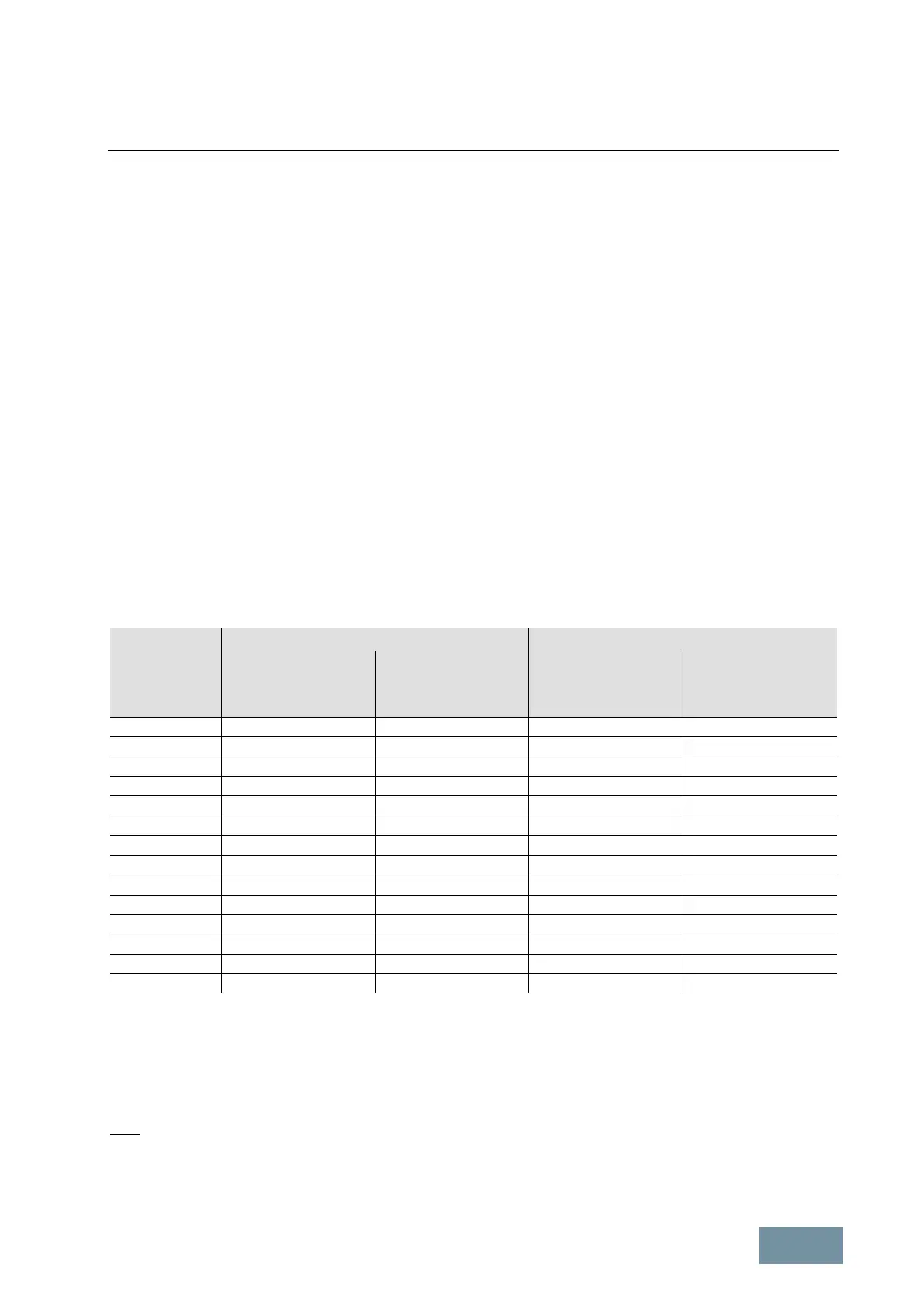
The required cable cross-section depends on the amperage which flows through the cable. The permissible current
loading of cables is defined, for example, in IEC 60364-5-52. It depends on ambient conditions such as the
temperature, but also on the routing method. An important factor to consider is whether cables are routed singly and
are therefore relatively well ventilated, or whether groups of cables are routed together. In the latter instance, the
cables are much less well ventilated and might therefore heat one another to a greater degree. For the relevant
correction factors applicable to these boundary conditions, please refer to IEC 60364-5-52. The table below provides
a guide to the recommended cross-sections (based on IEC 60364-5-52) for PVC-insulated, 3-wire copper and
aluminum cables, a permissible conductor temperature of 70°C (e.g. Protodur NYY or NYCWY) and an ambient
temperature of 40°C.
Cross-section
of 3-wire cable
[mm
2
]
Copper cable Aluminum cable
Single routing
[A]
Groups of cables
routed in parallel
1)
[A]
Single routing
A]
Groups of cables
routed in parallel
1)
[A]
3 x 2.5 22 17 17 13
3 x 4.0 30 23 23 18
3 x 6.0 37 29 29 22
3 x 10 52 41 40 31
3 x 16 70 54 53 41
3 x 25 88 69 68 53
3 x 35 110 86 84 65
3 x 50 133 104 102 79
3 x 70 171 133 131 102
3 x 95 207 162 159 124
3 x 120 240 187 184 144
3 x 150 278 216 213 166
3 x 185 317 247 244 190
3 x 240 374 292 287 224
1)
Maximum 9 cables routed horizontally in direct contact with one another on a cable rack
Current-carrying capacity of PVC-insulated, 3-wire copper and aluminum cables with a maximum permissible conductor
temperature of 70°C at an ambient temperature of 40°C according to IEC 60364-5-52
With higher amperages, cables must be connected in parallel.
Note:
The recommendations for the North American market in AWG or MCM must be taken from the appropriate NEC
(National Electrical Code) / CEC (Canadian Electrical Code) standards.
 Loading...


