Fundamental Principles and System Description
Engineering Information
SINAMICS Engineering Manual – November 2015
Ó Siemens AG
68/528
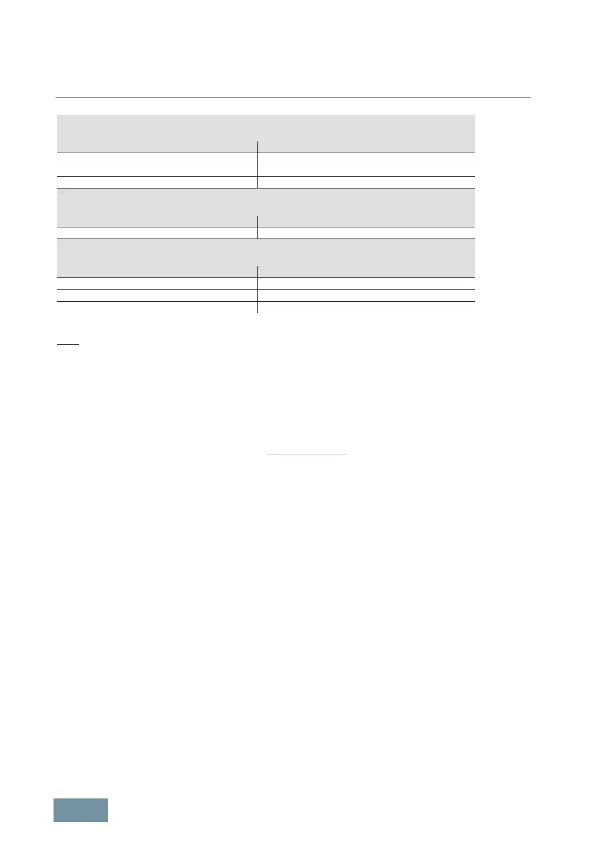
Total power factor λ for line-commutated SINAMICS converters and Infeeds
SINAMICS G130, G150, S120 Basic Infeed and S120 Smart Infeed
Relative short-circuit power RSC 100 % load
> 50 (strong line supply) ≈ 0.87
15 … 50 (medium line supply) ≈ 0.90
< 15 (weak line supply) ≈ 0.93
Total power factor λ for line-commutated SINAMICS converters with LHF compact
SINAMICS G150 with option L01
Relative short-circuit power RSC 100 % load
No significant dependency on RSC ≈ 0.985
Total power factor λ for self-commutated SINAMICS converters and Infeeds
SINAMICS S120 Active Infeed and S150 with factory setting of cosφ
1
to "1"
Relative short-circuit power RSC 100 % load
> 50 (strong line supply) ≈ 1.00
15 … 50 (medium line supply) ≈ 1.00
< 15 (weak line supply) ≈ 1.00
Typical values of the total power factor λ for SINAMICS converters and Infeeds
Note:
For the SINAMICS drives with unit transformers of the correct rating described in this engineering manual, the
relative short-circuit power RSC at the PCC of the converter as a result of the normal transformer impedance is
typically between RSC = 25 (transformer with v
k
= 4 %) and RSC = 15 (transformer with v
k
= 6.5 %).
1.3.1.2 Method of calculating the required apparent power S of a unit transformer
The required apparent power S of the unit transformer can be practically calculated with relative ease using the
formula below:
MotorConverter
P
kS
hhl
**
*³
Key to formula:
· P Shaft power of the motor or output power of the matched converter
· η
Motor
Motor efficiency
· η
Converter
Converter efficiency
· λ Line-side total power factor
· k Factor which allows for the effects of transformer stray losses as a result of line-
side harmonic currents
For output power of > approx. 50 kW, i.e. the lowest converter rating for which unit transformers are used, the
following values are accurate approximations:
· η
Motor
= 0.93 ... 0.97 η ≈ 0.93 for motor output of 50 kW rising to η ≈ 0.97 for motor output of 1MW
· η
Converter
≈ 0.98 For G130, G150 converters and converters with S120 Basic Infeeds or
S120 Smart Infeeds
· η
Converter
≈ 0.96 For S150 converters and converters with S120 Active Infeeds
· λ ≈ 0.93 For G130, G150 converters and S120 Basic Infeeds and S120 Smart Infeeds
· λ = 1 or λ = cos φ
AI
For S150 converters and units with Active Infeed:
λ = 1, if cos φ
AI
= 1 is parameterized with an Active Infeed (factory setting),
λ = cos φ
AI
, if cos φ
AI
≠ 1 is parameterized with an Active Infeed
· k = 1.20 For systems with a standard distribution transformer and G130 without LHF,
G150 without LHF, S120 Basic Infeeds and S120 Smart Infeeds
· k = 1.15 For systems with a standard distribution transformer and
G130 or G150 with Line Harmonics Filters (LHF and LHF compact)
· k = 1.10 For systems with a standard distribution transformer and
S150 and S120 Active Infeeds
· k = 1.00 When a converter transformer is used irrespective of the converter type
 Loading...


