SINAMICS S120 Cabinet Modules
Engineering Information
SINAMICS Engineering Manual – November 2015
Ó Siemens AG
400/528
The maximum permissible motor cable lengths for the different SINAMICS S120 Infeeds which ensure compliance
with the interference voltage limits defined for the above categories can be found in section "Line filters (RFI
suppression filters or EMC filters)" of chapter "Fundamental Principles and System Description".
To ensure that the converters comply with the limits defined for the above categories, it is absolutely essential that
the relevant installation guidelines are followed. The efficiency of the filters can be guaranteed only if the installation
instructions with respect to grounding and shielding are observed. For further details, please refer to section "Line
filters (RFI suppression filters or EMC filters)" in chapter "Fundamental Principles and System Description" and to
chapter "EMC Installation Guideline".
Line filters can be used only for SINAMICS S120 Cabinet Modules that are connected to grounded supply systems
(TN or TT with grounded neutral). On converters connected to non-grounded systems (IT systems), the standard
integrated line filter must be isolated from PE potential. This is done by removing the appropriate metal clip when the
drive is commissioned (see operating instructions). It is not possible to use the optional line filters (option L00) in non-
grounded systems to achieve compliance with the limits defined for category C2 by EMC product standard
EN 61800-3.
7.2.2.10 Parallel configuration
SINAMICS S120 Cabinet Modules are designed in such a way that standard devices can be operated in a parallel
connection at any time. A maximum possible configuration of up to four identical Line Modules or four identical Motor
Modules can be operated in a parallel connection for the purpose of increasing their output power.
Since the possibility of imbalances in current distribution cannot be completely precluded in parallel connections of
Cabinet Modules, the derating factors for current or power need to be taken into account when parallel connections
are configured:
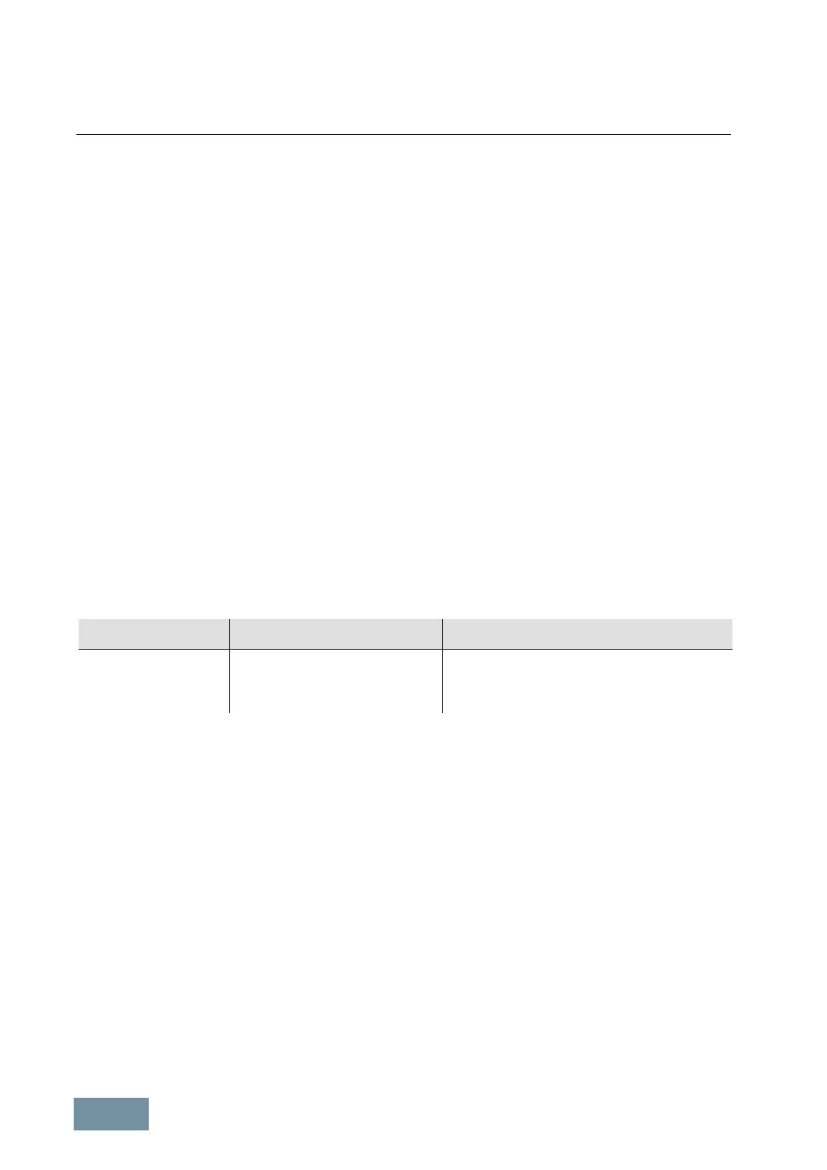
Designation Derating factor for parallel connection
of 2 to 4 modules
Max. permissible number of parallel-connected modules
Active Line Modules 0.95 4
Basic Line Modules 0.925 4
Smart Line Modules 0.925 4
Motor Modules Chassis 0.95 4
Only identical Line Modules or identical Motor Modules may be connected in parallel. "Identical" in this context means
that the voltage and current ratings, the output power and the versions of the Control Interface Modules CIM incl. the
relevant firmware releases must be the same. Additional boundary conditions (see section "Parallel connections of
converters" in chapter "Fundamental Principles and System Description") relevant to the decoupling of parallel-
connected modules must be taken into account in the configuring process.
Units in Booksize format cannot be connected in parallel.
Power units connected in parallel are controlled by a common Control Unit via DRIVE-CLiQ. It must be noted that the
DRIVE-CLiQ cables required to interconnect cabinets must be ordered separately (please see section “DRIVE-CLiQ
wiring”).
It is not permissible to operate mixtures of different Line Modules with the exception of a combination of Basic Line
Modules BLM and Smart Line Modules SLM (see section "SINAMICS Infeeds and their properties" in chapter
"Fundamental Principles and System Description").
 Loading...


