Fundamental Principles and System Description
Engineering Information
SINAMICS Engineering Manual – November 2015
Ó Siemens AG
139/528
1.9.4 Bearing currents caused by steep voltage edges on the motor
The steep voltage edges caused by the fast switching of the IGBTs in the inverter generate currents through the
internal capacitances of the motor. As a result of a variety of physical phenomena, these produce currents in the
motor bearings. In the worst-case scenario, these bearing currents can reach very high values, damage the bearings
and reduce the bearing lifetime.
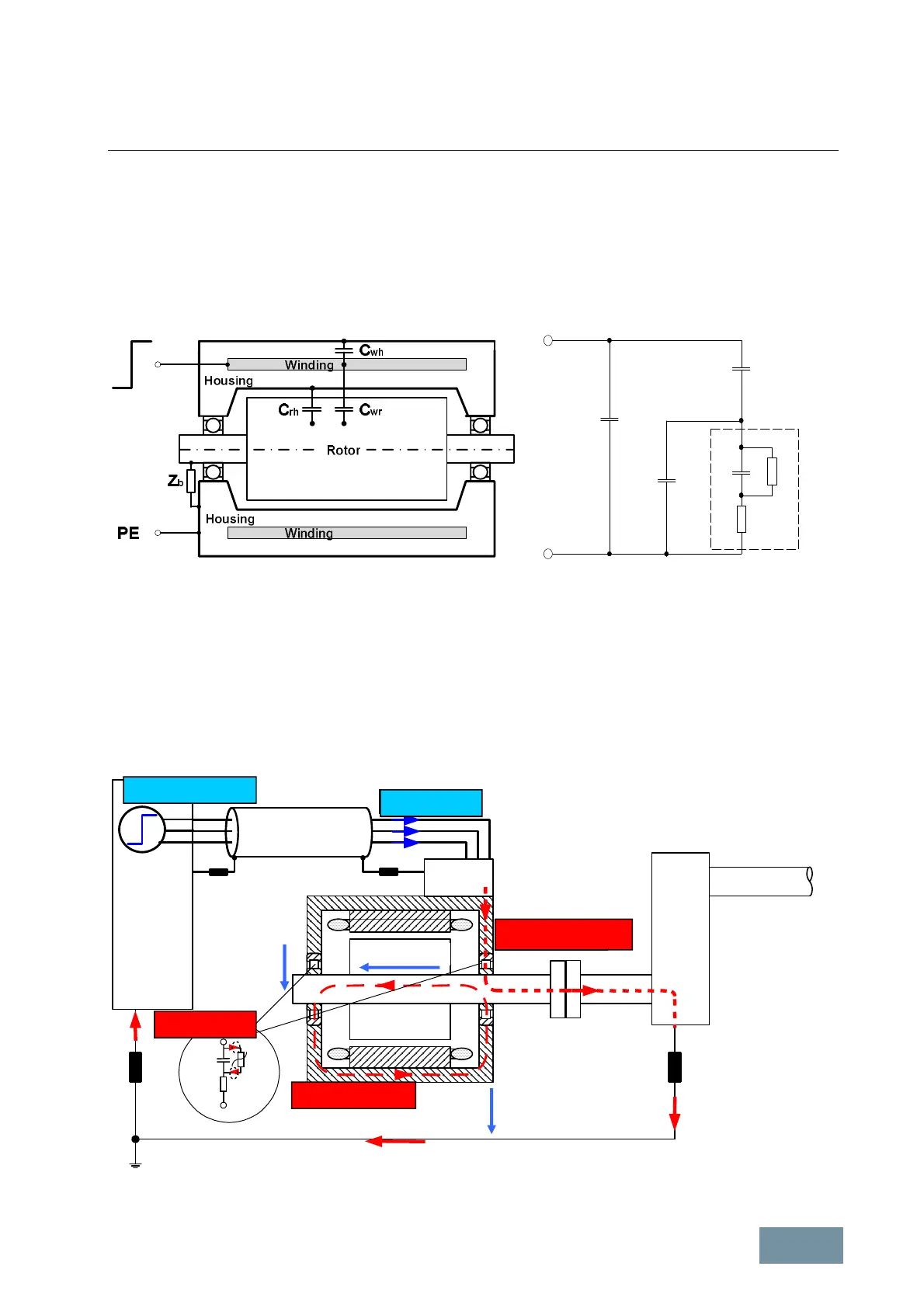
In order to describe the causes of bearing currents, a block diagram of the motor with its internal capacitances as well
as the electrical equivalent circuit diagram derived from it, are shown below.
Schematic representation of the motor with its internal capacitances and the associated electrical equivalent circuit
diagram
The stator winding has a capacitance C
wh
in relation to the motor housing and a capacitance C
wr
in relation to the
rotor. The rotor itself has a capacitance C
rh
in relation to the motor housing. The bearing can be defined by non-linear
impedance Z
b
. As long as the lubricating film acts as insulation, the bearing can be regarded as capacitance C
b
.
However, if the voltages on the bearing increase so much as to cause the lubricating film to break down, the bearing
starts to behave like a non-linear, voltage-dependent resistance Z
n
. Resistance R
b
represents the ohmic resistance of
the bearing rings and rolling elements.
The following diagram shows how the motor is integrated in the drive system as well as the various bearing current
types.
Integration of the motor into the drive system and representation of the various bearing current types
Spannungssprung
HF-Strom
Zirkularstrom
Rotorerdstrom
EDM-Strom
U
Gehäuse
U
Welle
U
Lager
Motor
Motor cable
Voltage edge
HF current
Rotor shaft current
EDM current
Circular current
V
Housing
V
Shaft
V
Bearing
C
wh
C
rh
C
b
R
b Z
b
Z
n
C
wr
 Loading...


