Fundamental Principles and System Description
Engineering Information
SINAMICS Engineering Manual – November 2015
Ó Siemens AG
29/528
In view of these properties, use of the V/f control method is recommended primarily for asynchronous motor drives
with low requirements of accuracy and dynamic response, and for asynchronous motor drives with limited speed
range and low torque requirements at low speeds. The V/f control method can be usefully employed up to an output
power of about 100 kW – 200 kW, and for multi-motor drives with asynchronous or SIEMOSYN motors. The higher
the motor power, the greater the tendency to oscillate at low frequencies. For this reason, drives of this type need to
be commissioned carefully. This applies in particular to the resonance damping function.
1.1.4.3 Field-oriented control modes
Field-oriented control is a sophisticated method of controlling three-phase motors. With field-oriented control, the
equations which describe the motor are not referred to the fixed coordinate system of the stator (α-β coordinates), but
instead to the rotating magnetic field of the rotor (d-q coordinates). In this rotating coordinate system which is rotor-
field-orientated, the stator current can be split into two components, i.e. the field-producing component I
d
and the
torque-producing component I
q
.
· The field-producing current component I
d
is responsible for the magnetic field in the motor and is thus
comparable to the excitation current in a DC motor.
· The torque-producing current component I
q
is responsible for the motor torque and is thus comparable to
the armature current in a DC motor.
The resulting control structure is therefore comparable to the DC motor. Thanks to the independent and direct control
of the field-producing current component I
d
and the torque-producing current component I
q
, a high degree of
accuracy and, more importantly, an excellent dynamic response are achieved with this control method.
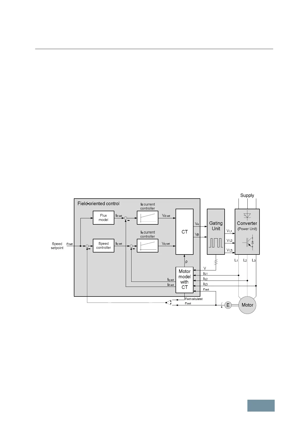
The diagram below illustrates the basic structure of the field-oriented control method for an asynchronous motor.
Diagram of the basic structure of the field-oriented control method for an asynchronous motor
The three measured actual motor current values I
L1
, I
L2
and I
L3
are converted into the two current components I
d act
and I
q act
of the rotating d-q coordinate system by means of a motor model which includes a coordinate transformation
(CT). The values of I
d act
and I
q act
are constant in the case of a symmetrical three-phase system in the motor with
purely sinusoidal motor currents which are out of phase by 120° in each case. They are compared to their setpoints
(I
d set
and I
q set
respectively) and applied to the I
d
current controller and I
q
current controller respectively. The
controller outputs provide the two voltage components V
d set
and V
q set
in the rotating d-q coordinate system. The
following coordinate transformation (CT) converts the two voltage components into the fixed α-β coordinate system.
The angle ρ between the rotating d-q coordinate system and the fixed α-βcoordinate system, which is required to
convert the coordinates, is calculated by the motor model. Using the two voltage components V
α
and V
β
, the gating
unit generates pulse patterns to control the IGBTs in the three phases of the power unit of the converter.
 Loading...


