SINAMICS S120 Cabinet Modules
Engineering Information
SINAMICS Engineering Manual – November 2015
Ó Siemens AG
390/528
Motor Modules Chassis Cooling air requirement Motor Module Chassis Cooling air requirement
Frame size
P
rated
at 400 V
[kW]
[m³/s]
Frame size
P
rated
at 690 V
[kW]
[m³/s]
Supply voltage 380 V to 480 V 3AC Supply voltage 500 V to 690 V 3AC
FX 110 0.17 FX 75 0.17
FX 132 0.23 FX 90 0.17
GX 160 0.36 FX 110 0.17
GX 200 0.36 FX 132 0.17
GX 250 0.36 GX 160 0.36
HX 315 0.78 GX 200 0.36
HX 400 0.78 GX 250 0.36
HX 450 0.78 GX 315 0.36
JX 560 1.08 HX 400 0.78
JX 710 1.08 HX 450 0.78
JX 800 1.08 HX 560 0.78
JX 710 1.08
JX 800 1.08
JX 900 1.08
JX 1000 1.08
JX 1200 1.08
Booksize Cabinet Kits Cooling air requirement
Frame size I
[A] [m³/s]
Supply voltage 380 V to 480 V 3AC
100mm
3
1)
0.008
200mm 2*3
0.008
100mm 5
0.008
200mm 2*5
0.008
100mm 9 0.008
200mm 2*9
0.008
100mm 18 0.008
200mm 2*18
0.016
100mm 30 0.016
200mm 45 0.031
200mm 60 0.031
200mm 85 0.044
300mm 132 0.144
300mm 200
0.144
Central Braking Modules Cooling air requirement
Frame size P
[kW] [m³/s]
Supply voltage 380 V to 480 V 3AC
Supply voltage 500 V to 600 V 3AC
Supply voltage 660 V to 690 V 3AC
400mm 500-1200 0.14
1) Production of these Booksize Cabinet Kits discontinued on 1st October 2013
7.2.2.6 Auxiliary power requirements
Air-cooled S120 Cabinet Modules require an auxiliary power supply (line voltage 1AC, 230 V 1AC, 24 V DC) in order
to operate correctly. The power requirement on every voltage level must be taken into account at the configuring
stage and supplied from external sources. Fuse protection for the auxiliary energy must also be provided externally.
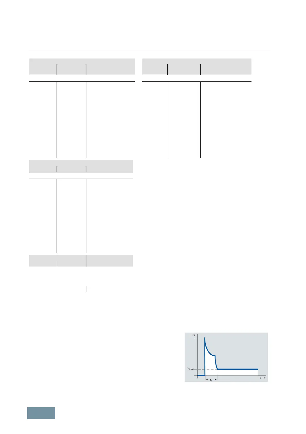
When selecting the external 24 V supply, it must be noted that the
capacitors in the electronics power supplies of all connected Cabinet
Modules must be charged when the power supply is switched on. The
24 V supply must therefore initially supply a peak current to charge these
capacitors. This peak current might correspond to a multiple of the
current I
DC ext
which is calculated from the sum of the values for all
connected Cabinet Modules as given in the tables on the following
pages. Account must be taken of this peak current when protective
devices such as miniature circuit breakers are installed. The peak current
flows for a period t
e
lasting only a few 100 ms. The peak value is
determined by the impedance of the external 24 V supply or its
electronically limited maximum current.
Typical current waveform when the
external 24 V supply is switched on
 Loading...


