SINAMICS S120
Engineering Information
SINAMICS Engineering Manual – November 2015
Ó Siemens AG
354/528
6.4.4 Cable installation
DRIVE-CLiQ cables must be installed in accordance with the rules specified for signal cables (see the relevant notes
in chapter "EMC Installation Guideline").
Since the DRIVE-CLiQ cables supplied with the products and available to order from the catalogs have special
properties and feature shield bonding integrated in the plug-in connector, no extra shield bonding for the DRIVE-CLiQ
cables needs to be provided in the cabinet. The cables should be installed where possible in zones C and D of a
cabinet (see corresponding note in chapter "EMC Installation Guideline").
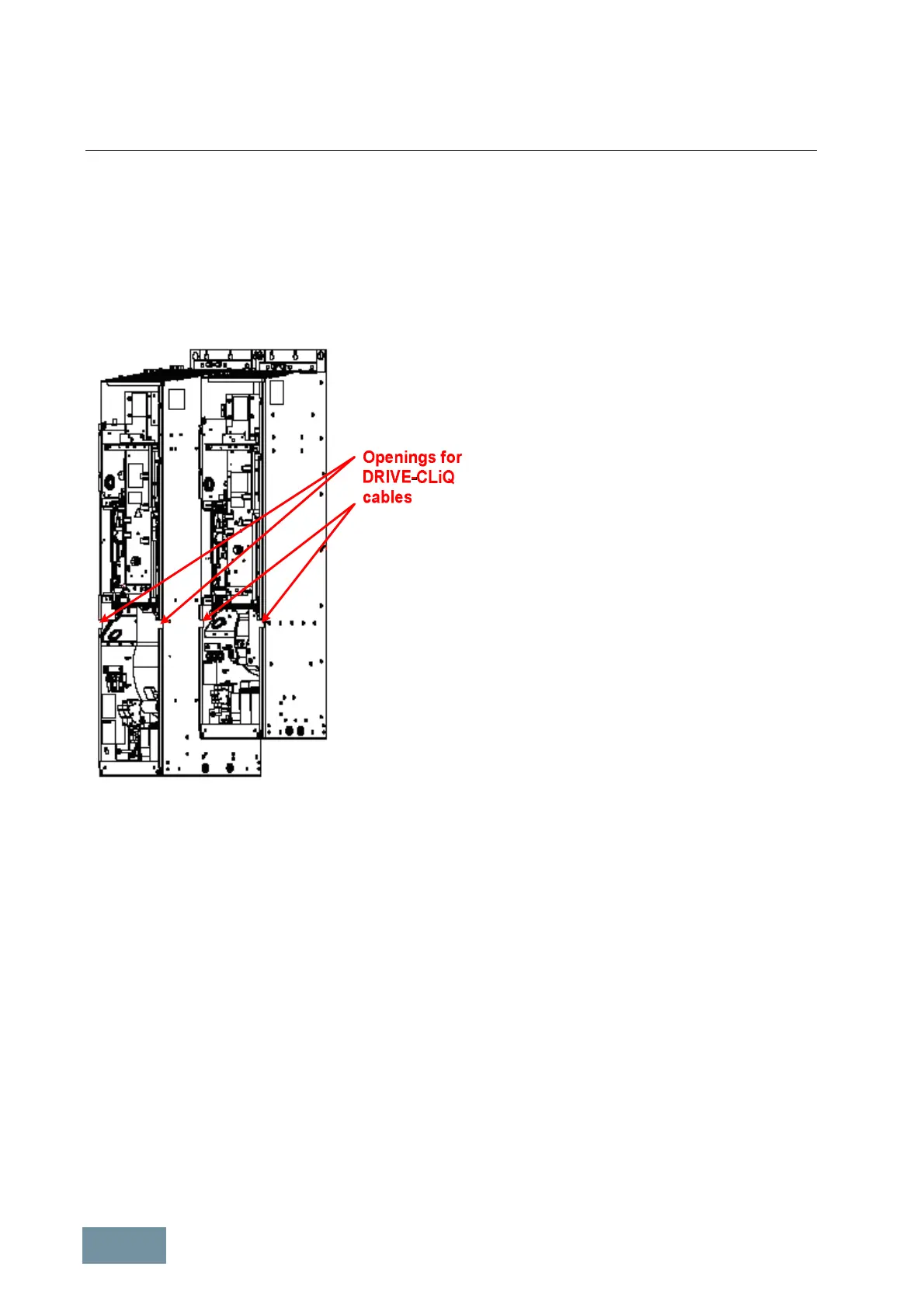
The DRIVE-CLiQ cable connectio
Unit position are located in the center of
unit on Chassis module
s. The cables can be routed
directly to the power unit by side openings on the
Chassis unit. The differe
nces in depth of the various
frame sizes must be taken into
difference in depth is about 200 mm.
The picture
on the left shows these openings
illustrated by the example of Motor Modules in
sizes
FX and GX. The cables supplied as standard
with the equipment can be easi
these openings.
Additional cables may be required, for example, if
they need to be routed over cross-beams or alon
other routes. In this case
, these cables need to be
calculated and ordered individually.
Openings for cable installation in the Power Units in Chassis format
Example of how to calculate and to route the required DRIVE-CLiQ cables
In this example, a drive configuration comprising four Motor Modules of frame size FX, supplied by an Active Line
Module of frame size GX with an Active Interface Module of frame size GI, must be connected up using DRIVE-CLiQ
cables. The cabinet layout is illusted in the diagram below.
The Control Unit must be latched into the lugs provided on the left-hand side of the Active Line Module. The Active
Interface Module must be installed on the left and at a distance of ≥ 100 mm from the Active Line Module so that the
Control Unit connections can still be accessed.
The Voltage Sensing Module VSM (in the Active Interface Module) is connected to the Control Interface Module CIM
of the Active Line Module using the cable [1] which is 0.95 m in length and supplied with the Active Interface Module.
The Control Unit is connected to the Active Line Module by means of the DRIVE-CLiQ cable [2] (0.6 m in length)
which is supplied with the Active Line Module. The first Motor Module is connected to the Control Unit with the
DRIVE-CLiQ cable [3] (1.45 m in length) which is supplied with the Active Interface Module. The DRIVE-CLiQ cables
from the Control Unit to the Active Line Module and the first Motor Module must be routed through the rubber sleeve
on the left-hand side of the Active Line Module. The connections between adjacent Motor Modules are made with the
DRIVE-CLiQ cable [2] (0.6 m in length) which is supplied as an accessory with every Motor Module of frame size FX.
 Loading...


