SINAMICS S120 Cabinet Modules
Engineering Information
SINAMICS Engineering Manual – November 2015
Ó Siemens AG
454/528
The Motor Modules are then arranged on the left and right of the Infeeds with the Heat Exchanger Modules installed
on the far left or right of the cabinet line-up, as illustrated in the following configuration examples.
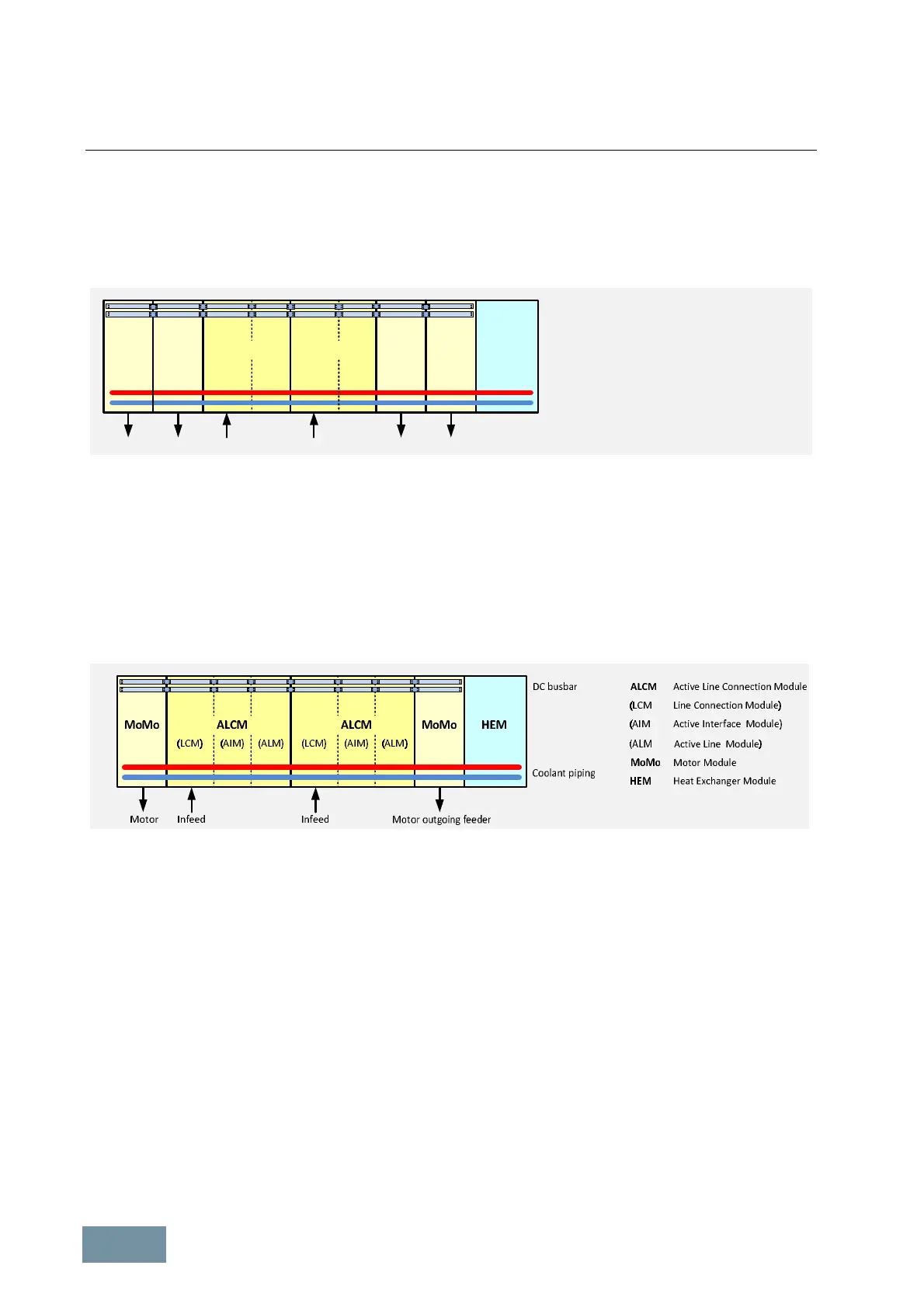
7.3.3.5 Examples of Cabinet Modules arrangements
12-pulse parallel connection of two Basic Line Connection Modules supplied by a three-winding transformer
DC busbar
Coolant piping
Infeed 1 Motor outgoing feeder
BLCM
(LCM)(BLM)
MoMo MoMo HEM
BLCM
(LCM
(BLM
MoMo
HEM
Basic Line Connection Module
Line Connection Module)
Basic Line Module)
Motor Module
Heat Exchanger Module
Infeed 2
BLCM
(LCM)(BLM)
Motor outgoing feeder
MoMo MoMo
With this configuration, option M88 must be ordered for each of the Basic Line Connection Modules in order to
establish a continuous DC busbar through the parallel-connected Infeeds. In the case of cabinet line-ups with very
high outputs, it may be necessary to divide the cooling circuit into two separate circuits and install two Heat
Exchanger Modules. These must then be installed at the beginning and the end of the line-up.
A 12-pulse parallel connection supplied by a three-winding transformer has minor harmonic effects on the supply.
The two secondary windings must be phase-shifted by 30° (vector group e.g. Dy5d0 or Dy11d0).
When Basic Line Connection Modules are connected in parallel, a current derating factor of 7.5 % applies due to
potential current imbalances.
Parallel connection of two Active Line Connection Modules supplied by a two-winding transformer
With this configuration, option M88 must be ordered for each of the Active Line Connection Modules in order to
establish a continuous DC busbar through the parallel-connected Infeeds. In the case of cabinet line-ups with very
high outputs, it may be necessary to divide the cooling circuit into two separate circuits and install two Heat
Exchanger Modules. These must then be installed at the beginning and the end of the line-up.
When Active Line Connection Modules are connected in parallel, a current derating factor of 5 % applies due to
potential current imbalances.
7.3.3.6 Door opening angle
The doors on Cabinet Modules have the same width as the cabinets themselves. Cabinets up to a width of 600 mm
have a single door which is hinged on the right-hand side. Wider cabinets have double doors.
The following information is important, for example, in the planning of emergency exit routes:
· Maximum door width: 600 mm
· Maximum door opening angle:
§ For degrees of protection IP23 and IP43 with ventilation openings
in the cabinet doors 110 °
§ For degrees of protection IP21 and IP55 without ventilation openings
in the cabinet doors 135 °
 Loading...


