Fundamental Principles and System Description
Engineering Information
SINAMICS Engineering Manual – November 2015
Ó Siemens AG
134/528
1.9.3 Increased voltage stress on the motor winding as a result of long motor cables
The DC link voltage V
DCLink
of the converter or inverter is the starting point for calculating the voltage stress between
the phases of the motor winding.
The IGBTs used in SINAMICS inverters are connecting the DC link voltage V
DCLink
to the inverter output with a rise
time of T
r
≥ 0.1 ms. In the case of a 690 V supply with a DC link voltage of virtually 1000 V, this corresponds to a
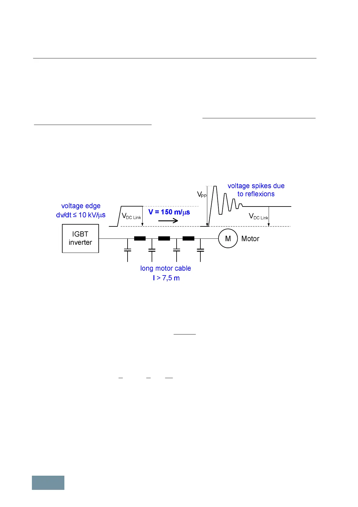
voltage edge (phase-to-phase) with a rate-of-rise of dv/dt ≤ 10 kV/ms. The typical average values of voltage rate-of-
rise for SINAMICS are dv/dt = 3 kV/ms – 6 kV/ms. If the inverter output is connected directly to the motor cable, i.e. no
motor-side options such as motor reactors, dv/dt filters plus VPL, dv/dt filters compact plus VPL or sine-wave filters
are installed at the inverter output, this phase-to-phase voltage edge moves with a speed of about 150 m/ms (≈ half
the speed of light) along the motor cable towards the motor.
Since the impedance Z
W Motor
of the motor is significantly higher than the impedance Z
W Cable
of the motor cable, the
voltage edge arriving at the motor terminals is reflected, causing brief voltage spikes V
PP
in the phase-to-phase
voltage of the motor terminals which can reach values of twice the DC link voltage V
DCLink
.
Characteristic phase-to-phase voltage at the inverter output and motor winding when a long motor cable is used
The voltage spike due to reflection initially increases in proportion to the motor cable length and reaches its maximum
value when the rise time T
r
of the voltage edge at the inverter output is less than twice the propagation time t
Prop
along the motor cable, i.e. when
v
Cable
opr
l
tT
=×<
2
2
Pr
With a minimum rise time of the voltage edge of T
r
= 0.1 µs and a propagation speed along the motor cable of
v ≈ 150 m/ms, the critical cable length at which the voltage spikes due to reflection can theoretically reach their
maximum value can be calculated as
ms
s
m
Tl
r
Cable 5.71.0150
2
1
2
1
=××××>
m
m
=v
In practice, voltage spikes due to reflection typically reach their maximum values with motor cable lengths of around
20 to 25 m and more. It is therefore true to say that in most applications where the inverter output is directly
connected to the motor cable and no motor reactors or motor filters are installed, significant voltages spikes due to
reflection must be expected at the motor.
If it is assumed that voltage spikes due to reflections will reach their maximum value with the length of motor cables
used, the absolute magnitude of the reflection-related voltage spikes V
PP
in the phase-to-phase voltage at the motor
is dependent on two influencing variables, i.e.
· the DC link voltage V
DC Link
of the inverter and
· the reflection factor r at the motor terminals.
 Loading...


