Fundamental Principles and System Description
Engineering Information
SINAMICS Engineering Manual – November 2015
Ó Siemens AG
17/528
If we consider all three phases, there is a total of 2³ = 8 switching states in the inverter, and the effect of these states
in the motor can be defined by voltage phasors.
Switching states of the
inverter
Phase
L1
Phase
L2
Phase
L3
V
+ - -
V
+ + -
V
- + -
V
- + +
V
- - +
V
+ - +
V
+ + +
V
- - -
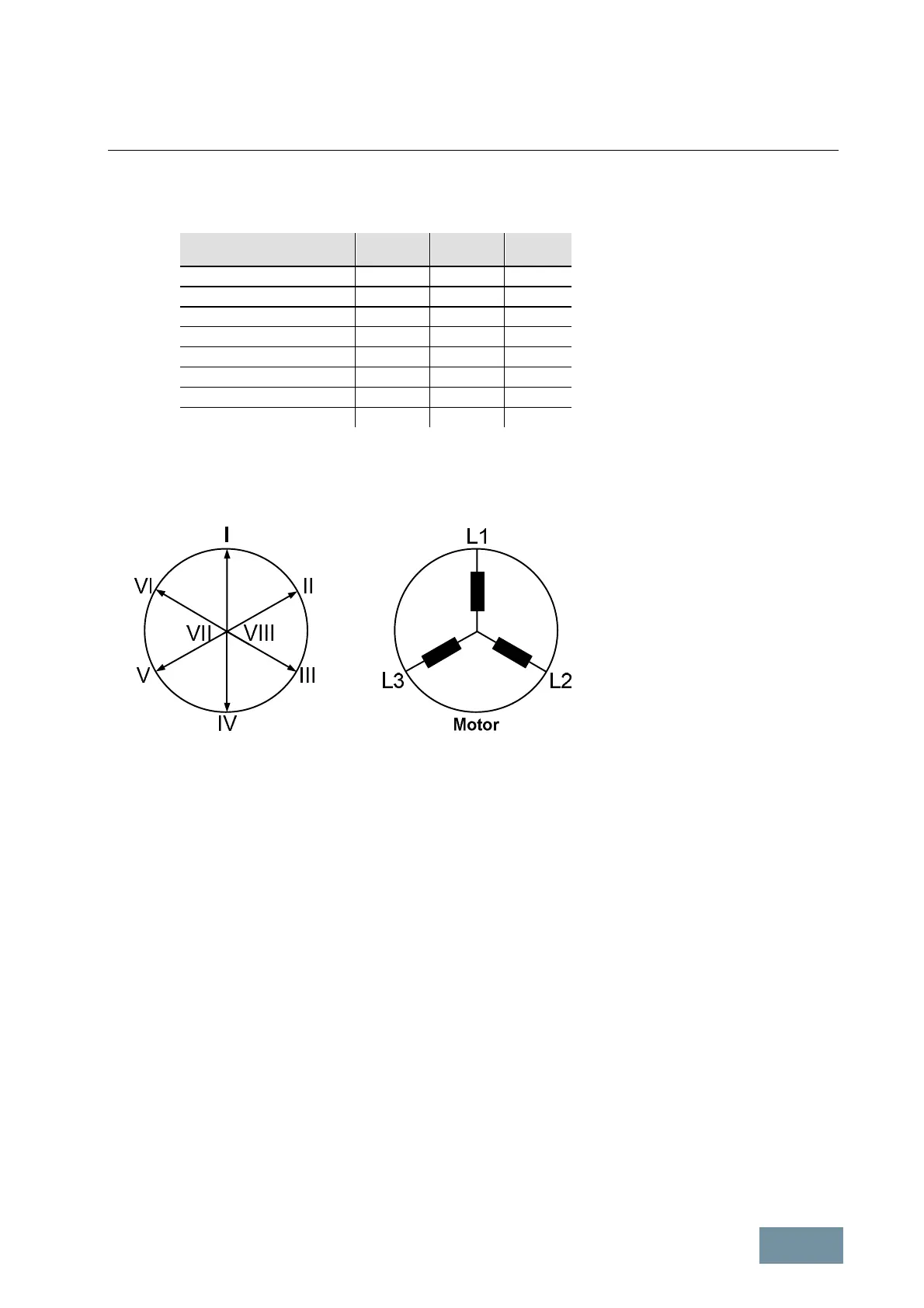
If, for example, phase L1 is connected to the positive DC link voltage, and phases L2 and L3 to the negative voltage
so as to produce switching state V
1
, the resultant voltage phasor points in the direction of motor phase L1 and is
designated phase I. The length of this phasor is determined by the DC link voltage.
Representation of resultant motor voltages as phasor
If the switching state changes from V
1
to V
2
, then the voltage phasor rotates clockwise by an angle of 60°el. due to
the change in potential at terminal L2. The length of the phasor remains unchanged.
In the same way, the relevant voltage phasors are produced by switching combinations V
3
to V
6
. Switching
combinations V
7
and V
8
produce the same potential at all motor terminals. These two combinations therefore produce
voltage phasors of "zero" length (zero voltage phasor).
1.1.2.1 Generation of a variable voltage by pulse-width modulation
Voltage and frequency must be specified in a suitable way for a certain operating state of the motor, characterized by
speed and torque. Ideally, this corresponds to control of the voltage vector V(wt) on a circular path with the speed of
rotation w = 2
*
p
*
f and adjusted absolute value. This is achieved through modulation of the actual settable voltage
space vectors (pulse-width modulation). In this way, the momentary value V(wt) is formed by pulses of the adjacent,
actual settable voltage space vectors and the voltage zero.
The solid angle is set directly by varying the ratio of the ON durations (pulse-width) of adjacent voltage vectors, the
desired absolute value by varying the ON duration of the zero voltage vector. This method of generating gating
signals is called space vector modulation SVM. It is used in all units described in this engineering manual. Space
vector modulation provides sine-modulated pulse patterns.
 Loading...


