Fundamental Principles and System Description
Engineering Information
SINAMICS Engineering Manual – November 2015
Ó Siemens AG
18/528
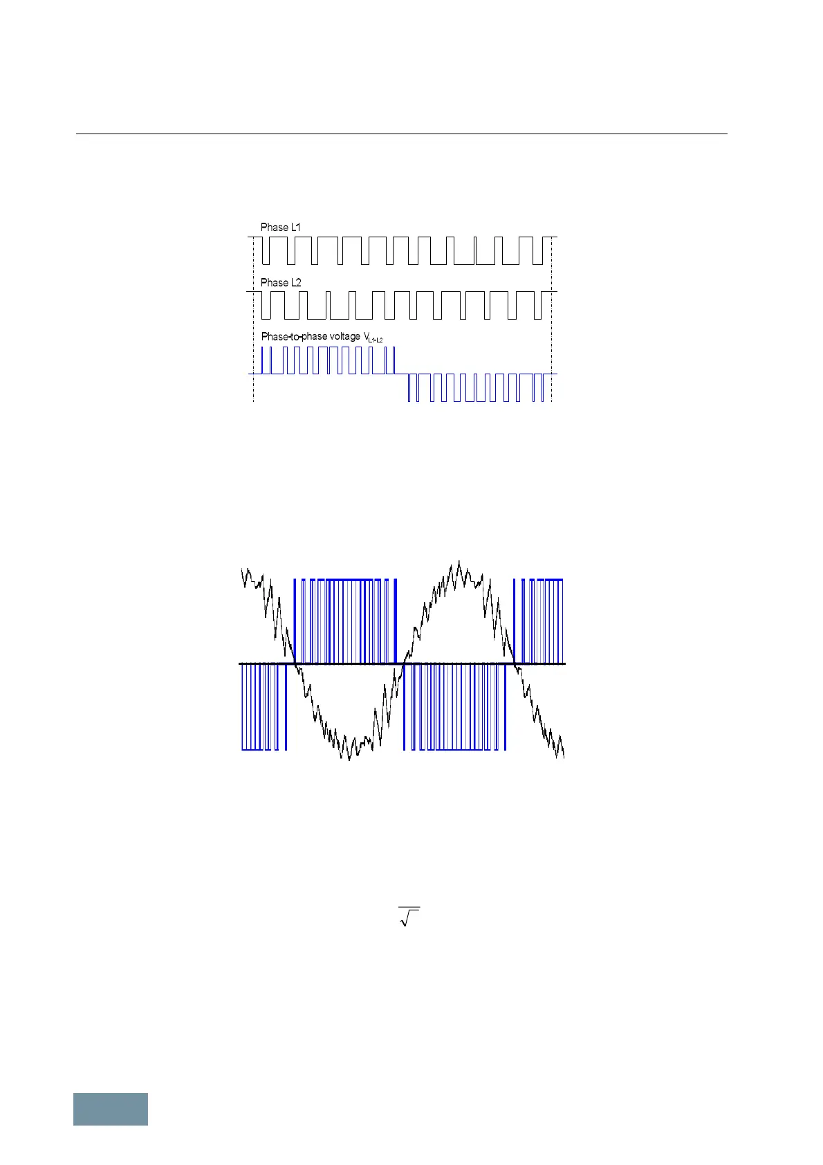
The following diagram illustrates how the voltages in phases L1 and L2 plus output voltage V
L1-L2
(phase-to-phase
voltage) are produced by pulse-width modulation or space vector modulation and shows their basic time
characteristics. The frequency with which the IGBTs in the inverter phases are switched on and off is referred to as
the pulse frequency or clock frequency of the inverter.
Timing of the gating signal sequence for the IGBTs in the inverter phases L1 and L2 plus the associated output voltage
(phase-to-phase voltage) V
L1-L2
. The amplitude of the voltage pulses corresponds to the DC link voltage.
The diagram below shows the time characteristic (in blue) of one of the three output voltages of the inverter (phase-
to-phase voltage) and the resulting current (in black) generated in one of the three motor phases when a standard
asynchronous motor with a rated frequency of 50 Hz or 60 Hz is used and the inverter is operating with a pulse
frequency of 1.25 kHz. The diagram shows that the smoothing effect of the motor inductances causes the motor
current to be virtually sinusoidal, despite the fact that the motor is supplied with a square-wave pulse pattern.
Motor voltage (phase-to-phase) and motor current with space vector modulation
1.1.2.2 Maximum attainable output voltage with space vector modulation SVM
Space vector modulation SVM generates pulse patterns which approximate an ideal sinusoidal motor voltage through
voltage pulses with constant amplitude and corresponding pulse-duty factor. The peak value of the maximum
(fundamental) voltage that can be attained in this way corresponds to the amplitude of the DC link voltage V
DCLink
.
Thus the theoretical maximum motor voltage with space vector modulation which results is:
DCLink
SVM
VV ×=
2
1
max
The amplitude of the DC link voltage V
DCLink
is determined by the method of line voltage rectification. With line-
commutated rectifiers used with SINAMICS G130 and G150 and also with S120 Basic Line Modules, it averages
1.41*V
Line
with no load, 1.35*V
Line
with partial load and 1.32*V
Line
.with full load. Thus with the true DC link voltage
amplitude of V
DCLink
≈ 1.32
*
V
Line
at full load, the motor voltage theoretically attainable at full load with space vector
modulation without overmodulation is:
V
SVM max
= 0.935
*
V
Line
.
 Loading...


