Fundamental Principles and System Description
Engineering Information
SINAMICS Engineering Manual – November 2015
Ó Siemens AG
39/528
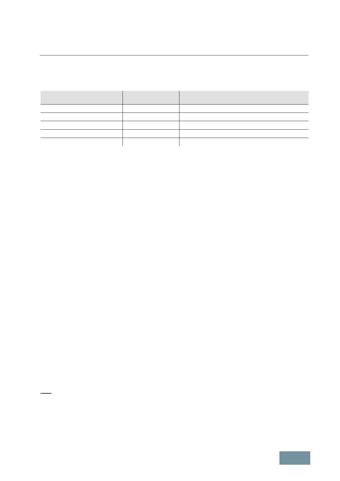
The following table lists the standard SCCR values for electric drives ("Motor Controllers") according to UL 508A, as
well as the SCCR values of the approved SINAMICS G130 converter Chassis units and the approved modular
SINAMICS S120 built-in units in Chassis format.
Output power of the electric drive
“Motor Controller”
Standard SCCR values
according to UL 508A
SCCR values of the UL-approved Built-in units
SINAMICS G130 and S120 in Chassis format
51 – 200 hp (38 – 149 kW) 10 kA 65 kA
201 – 400 hp (150 – 298 kW) 18 kA 65 kA
401 – 600 hp (299 – 447 kW) 30 kA 65 kA
601 – 900 hp (448 – 671 kW) 42 kA 84 kA
901 – 1500 hp (672 – 1193 kW) 85 kA 170 kA
Standard SCCR values according to UL 508A and SCCR values of the approved SINAMICS G130 and S120 Chassis units
1.2.4 Maximum short-circuit currents (SCCR according to IEC) and minimum short-circuit currents
The following tables specify the maximum permissible line-side short-circuit currents and the recommended minimum
line-side short-circuit currents for SINAMICS G130 converter Chassis units, SINAMICS G150 and S150 converter
cabinet units and for the SINAMICS S120 Infeeds in Chassis and Cabinet Modules format.
The maximum permissible short-circuit currents are the line-side short-circuit currents for which the units are
designed. Provided that the maximum permissible short-circuit currents are not exceeded, the equipment will not
develop any defects as a result of excess current or overheating in the event of a short circuit. This is why it is
important to ensure that the supply systems to which the SINAMICS units are connected are not capable of supplying
higher short-circuit currents than the maximum permissible short-circuit currents of the connected SINAMICS
converters. Since the incoming busbars as well as the fuse switch disconnectors and circuit breakers which might
also be installed each have different short-circuit current limits, the weakest component in each case determines the
permissible short-circuit current for all other components. In consequence, the values stated in the tables for the
cabinet units are dependent on whether the units have no line-side fuse elements or whether they are equipped with
the main switches including 3NE1 fuses or 3WL circuit breakers that are available as option L26.
The recommended minimum short-circuit currents are the minimum line-side short-circuit currents which should
be produced at the point of common coupling of the SINAMICS units by the supply system in the event of a short
circuit in order to ensure tripping of the line-side fuses of type 3NE1 within approximately half a line period and of the
circuit breakers of type 3WL within around 100 ms (types 3NE1 and 3WL are recommended in catalogs D 11 and
D 21.3). In the next column of the table, the associated minimum relative short-circuit power RSC
min
at the point of
common coupling is specified - this is defined as the ratio between the minimum required short-circuit power S
K Line
at
the point of common coupling and the rated apparent power (fundamental apparent power) S
converter
of the connected
converter (or the connected Infeed). The last column in the table specifies the maximum permissible relative short-
circuit voltage v
k max
of the supply system (per unit impedance) which corresponds to the minimum relative short-
circuit power RSC
min
. Irrespective of the value for the minimum relative short-circuit power RSC
min
, the maximum
relative short-circuit voltage v
k max
of the supply system (per unit impedance) should not be greater than ≈ 10 % in
order to limit the harmonic effects on the supply system to an acceptable level.
Note:
The minimum short-circuit current specifications are the values recommended in order to ensure rapid tripping of the
line-side fuses of type 3NE1 within approximately half a line period. If a particular system configuration is such that
the short-circuit currents produced by the system are slightly lower than the recommended values, then the fuses will
take longer to respond. The total breaking I
2
t value therefore increases and the level of protection for the thyristors
and diodes in the rectifiers might be reduced as a result. The fuses are nevertheless still guaranteed to trip provided
that the minimum short-circuit currents correspond to around 80 to 90% of the recommended values.
 Loading...


