Fundamental Principles and System Description
Engineering Information
SINAMICS Engineering Manual – November 2015
Ó Siemens AG
126/528
Motor
Module
Motor
Module
Motor
Module
Motor
Module
Motor
Module
Motor
Module
S120 Infeed
DC busbar
Motor
Module
Motor
Module
Motor
Module
Motor
Module
Motor
Module
Motor
Module
DC busbar
Motor
Module
Motor
Module
high power rating
high power rating high power rating
low power rating low power rating
low power rating low power rating
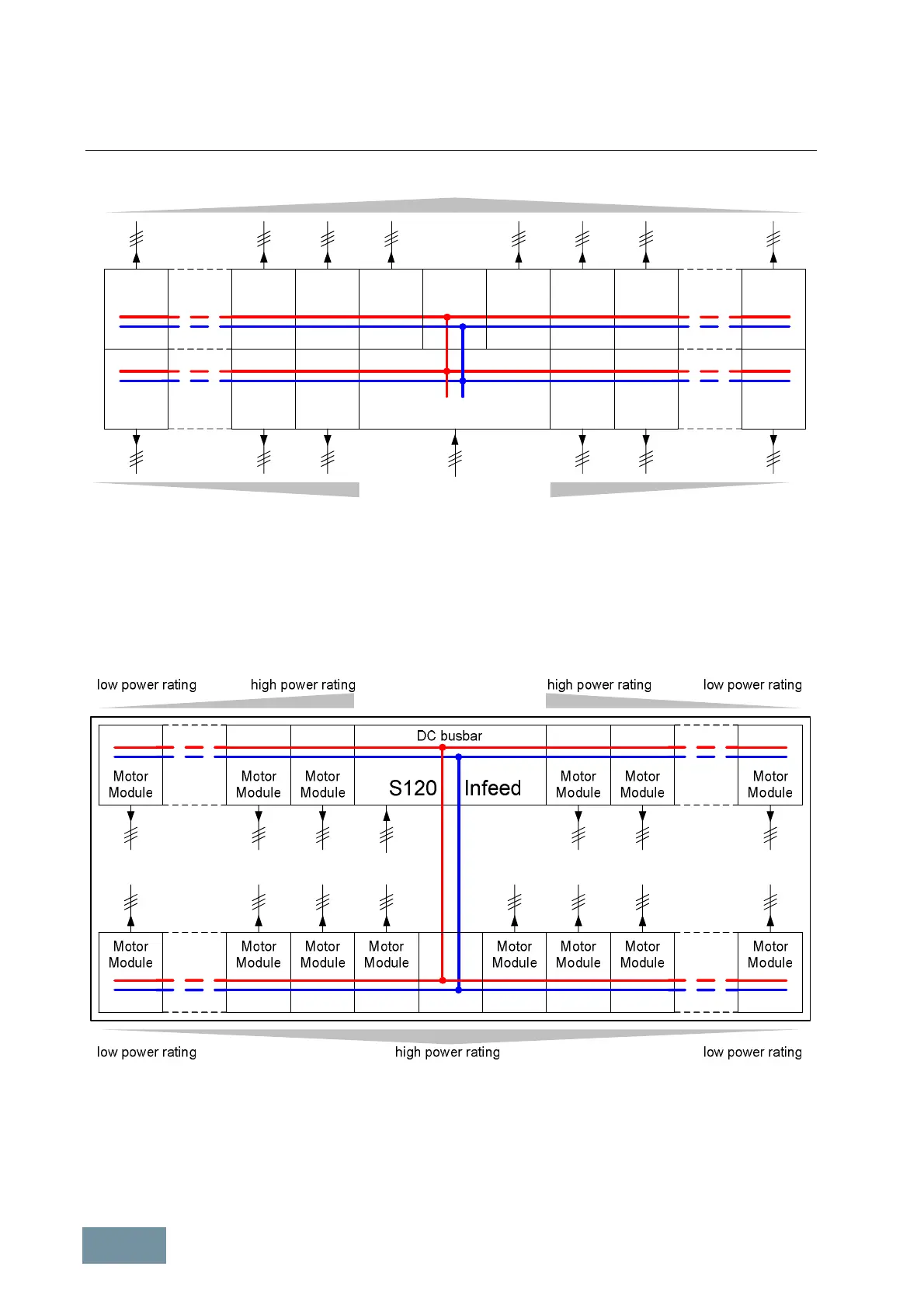
Example 3: Linear arrangement of the DC busbar in two sub-configurations / back-to-back arrangement
Instead of arranging two sub-configurations back-to-back as illustrated in example 3, it is also possible to select an
arrangement with two opposite configurations as illustrated in example 4. This would allow, for example, one sub-
configuration to be mounted on one wall of the converter room and the other sub-configuration to be mounted on the
opposite wall.
Example 4: Linear arrangement of the DC busbar in two sub-configurations / opposite arrangement
Some applications essentially require a drive configuration comprising two sub-configurations situated a long
distance apart. The sub-configurations must then be interconnected by means of long DC busbars or DC cabling, as
illustrated in example 5.
 Loading...


