Fundamental Principles and System Description
Engineering Information
SINAMICS Engineering Manual – November 2015
Ó Siemens AG
150/528
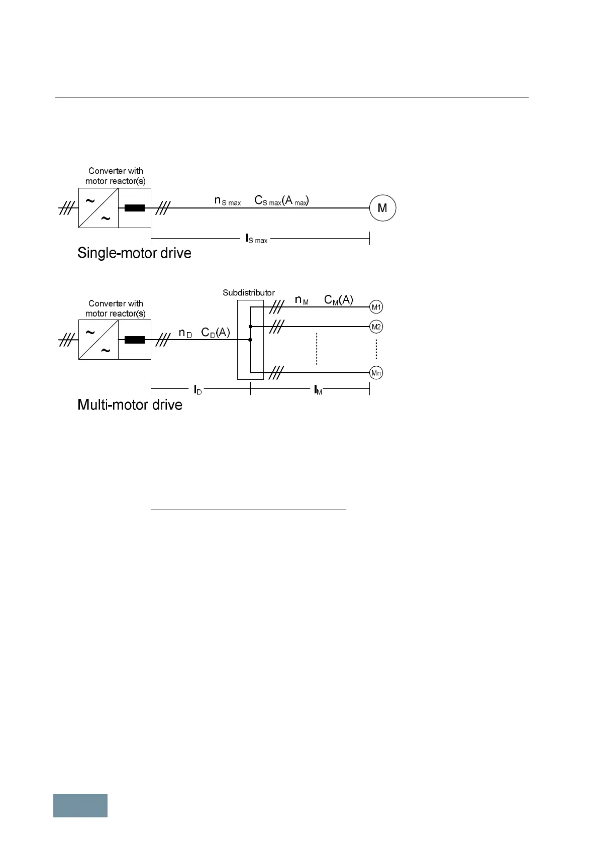
A method of calculating the permissible cable lengths for multi-motor drives l
M
based on the catalog data for single-
motor drives is described below.
The diagram explains the quantities and terms used for both single-motor and multi-motor drives.
Block diagram of single-motor drive and multi-motor drive with relevant quantities and terms
The permissible motor cable length per motor on a multi-motor drive is calculated with the fomula:
)(
)()(
maxmaxmaxmax
ACn
lACnlACn
l
MM
DDDSSS
M
×
××-××
=
Definition and meaning of applied quantities:
· l
M
Permissible cable length between the subdistributor and each motor in a multi-motor drive.
· n
S max
Maximum number of motor cables which can be connected in parallel in a single-motor drive. This
value can be found in the chapters on specific units or in the relevant catalogs.
· C
S max
(A
max
) Capacitance per unit length of a shielded motor cable with the maximum permissible cross-section
A
max
for a single-motor drive. This value can be found in the table on the next page and is
depending on the maximum permissible cross-section A
max
specified in the chapters on specific
units or the relevant catalogs.
· l
S max
Permissible motor cable length for single-motor drive as specified in the tables on the previous
page (depending on the number of motor reactors (1 or 2) and whether the cable is shielded or
unshielded).
· n
D
Number of parallel cables between the converter and subdistributor on a multi-motor drive.
· C
D
(A) Capacitance per unit length of the cable between the converter and subdistributor on a multi-motor
drive.
· l
D
Length of the cable between the converter and subdistributor on a multi-motor drive.
· n
M
Number of parallel cables on motor side of subdistributor = number of motors.
· C
M
(A) Capacitance per unit length of cables on motor side of subdistributor.
 Loading...


