Fundamental Principles and System Description
Engineering Information
SINAMICS Engineering Manual – November 2015
Ó Siemens AG
166/528
If the criteria described above are applied to the SINAMICS G130, G150 and S150 converters and to the SINAMICS
S120 inverter Motor Modules (Chassis and Cabinet Modules), then free load duty cycles are permissible whenever
the following conditions are fulfilled:
The short-time current I
ShortTime
must be limited to values less than 1.5
*
k
D*
I
H
.
(In the case of parallel connections of S120 Motor Modules, I
ShortTime
is the short-time current of one inverter section
or one Motor Module)
The current derating factor k
D
takes into account all influences which necessitate a reduction in the short-time current
of the converter or inverter:
IGBTParallelPulseTempD
kkkkk ×××= .
Key to equation:
· k
D
Current derating factor (total derating factor),
· k
Temp
Derating factor for increased ambient temperature in the 40 °C to 50 °C / 55 °C range,
· k
Pulse
Derating factor for pulse frequencies higher than the factory-set pulse frequency,
· k
Parallel
Derating factor for parallel operation of S120 Motor Modules,
· k
IGBT
Derating factor for periodic load duty cycles in order to protect against premature IGBT failure..
The derating factors k
Temp
and k
Pulse
are unit-specific and can be found in the appropriate catalogs or the unit-specific
sections of this engineering manual. With respect to the derating factor k
Pulse
, the information in section "Operation of
converters at increased pulse frequency" must be observed.
The derating factor k
Parallel
is generally 0.95 for SINAMICS S120 Motor Modules.
The derating factor k
IGBT
is unit-specific and must only be applied in the case of regularly recurring, periodic load duty
cycles (e.g. shears, presses, centrifuges, amusement rides in theme parks, etc.) in order to limit the temperature
swing ΔT
Chip
in the IGBT and thus to protect against premature IGBT failure.
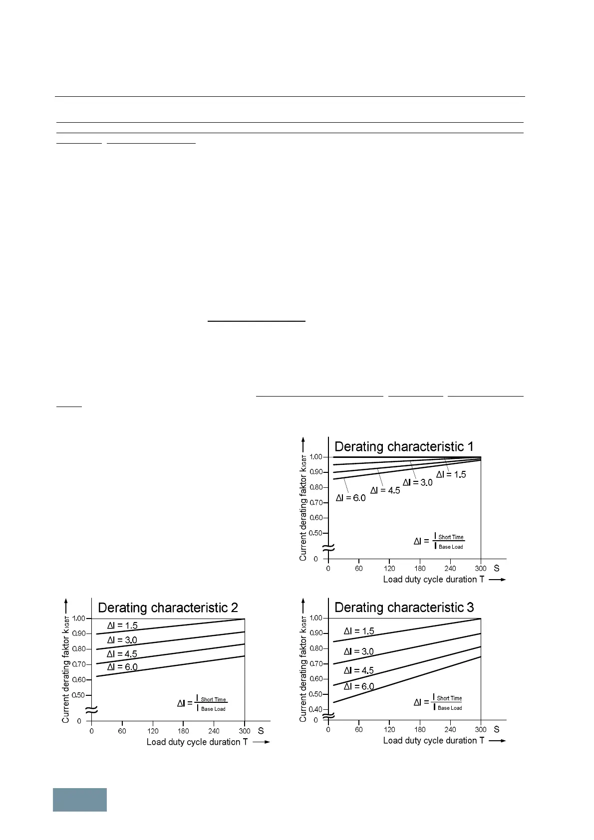
The following derating characteristics specify the
derating factor k
IGBT
as a function of the current ratio
ΔI = I
ShortTime
/ I
BaseLoad
and the load duty cycle duration
T.
The assignment between derating characteristics 1 to 3
and SINAMICS G130 and G150 converters, SINAMICS
S120 Motor Modules (air-cooled and liquid-cooled) and
SINAMICS S150 converters are given in the assignment
table on the following page.
Derating factor k
IGBT
as a function of the current ratio ΔI = I
Short Time
/ I
Base Load
and the load duty cycle duration T
 Loading...


