Fundamental Principles and System Description
Engineering Information
SINAMICS Engineering Manual – November 2015
Ó Siemens AG
91/528
Line Harmonics Filters compact should not be operated on supply systems with reactive current compensation
systems, nor in combination with other 6-pulse converters that are not equipped with Line Harmonics Filters, nor in
combination with devices that operate with pronounced phase angle control.
Line Harmonics Filters compact are suitable for both, 50 Hz and 60 Hz supply systems. If converters with a Line
Harmonics Filter compact are operated on 60 Hz supplies with voltages at the top end of the relevant permissible line
connection voltage range, the permissible upper line voltage tolerance is limited to +8 %, because the voltage at the
rectifier input is increased slightly relative to the line voltage as a result of the filter design.
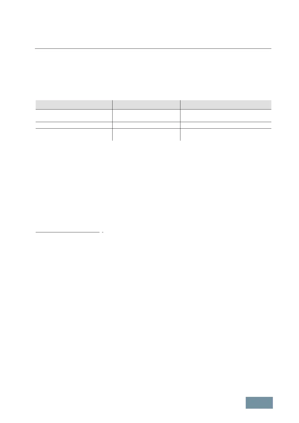
Line supply voltage range Line supply voltage Permissible upper line voltage tolerance
380 V – 480 V 3AC / 60 Hz up to 460 V / 60 Hz + 10 %
480 V / 60 Hz + 8 %
500 V – 600 V 3AC / 60 Hz up to 600 V / 60 Hz + 10 %
660 V – 690 V 3AC / 60 Hz up to 660 V / 60 Hz + 10 %
690 V / 60 Hz + 8 %
Permissible line voltage tolerances when converters with Line Harmonics Filters compact are operated on 60 Hz supplies
If a Braking Module is installed in a converter with a Line Harmonics Filter compact, the Braking Module must always
be set to the upper response threshold (corresponding to the factory setting). This setting must not be changed.
After the converter has been disconnected from the supply system, the filter capacitors must be almost fully
discharged before the converter may be connected to the supply again. This is why the converter is locked out from
reconnection to the supply for a period of 30 s. This lockout function is provided by a time relay on all SINAMICS
G150 converters with LHF compact (option L01).
For this reason, it is a standard feature of G150 converters with installed option L01 that they cannot be quickly
restarted after a power outage or a fault trip nor can the kinetic buffering function be used to bridge brief line dips or
failures which last for a period of < 30 s.
The restart delay time can however be reduced by use of the supplementary option L76 (quick discharge of filter
capacitors). Option L76 shortens the standard restart delay time from 30 s down to around 3 - 5 s.
Information about commissioning:
On converters with LHF compact, the dynamic response of the speed controller should not be set too high, i.e. the
speed controller gain setting K
p
should be in the lower range and the speed controller integral time T in the higher
range. Where appropriate, the filter time constant of the Vdc compensation (p1806) should be raised to values within
the range from approximately 20 ms to approximately 100 ms.
 Loading...


