NOTES:
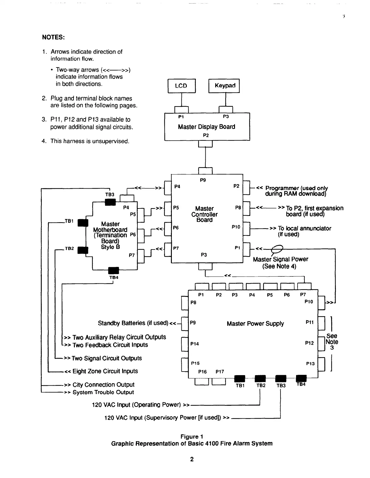
1. Arrows indicate direction of
information flow.
l
Two-way arrows (<:<-
>>I
indicate information flows
in both directions.
2. Plug and terminal block names
are listed on the following pages.
LCD
Keypad
3. Pll, P12 and P13 available to
power additional signal circuits.
Pl
P3
Master Display Board
P2
4. This harness is unsupervised.
Master
ansion
‘“IP q
cc- 22
TO P2,
tirst ex
Cotnt~olJer
board (if use
J
-am ”
>> To local annunciator
Master
r
Motherl
P3
p1 l--v
Master Signal Power
(See Note 4)
_ _
J
TB4
l-
I
I II II
II II II II I ,
_ Pl P2 P3 P4 P5 P6 P7
P8
PlO
-*a
Standby Batteries (if used) e<- P9
Master Power Supply
Pll
t
1
>> Two Auxiliary Relay Circuit Outputs
- See
** Two Feedback Circuit Inputs
P14
P12
_ N:te
*> Two Signal Circuit Outputs
Pl5
P13
-<< Eight Zone Circuit Inputs
- P16 P17
->a City Connection Output
-->> System Trouble Output
120 VAC Input (Operating Power) s>
120 VAC Input (Supervisory Power [if used]) 5,
/
Figure 1
Graphic Representation of Basic 4100 Fire Alarm System
2