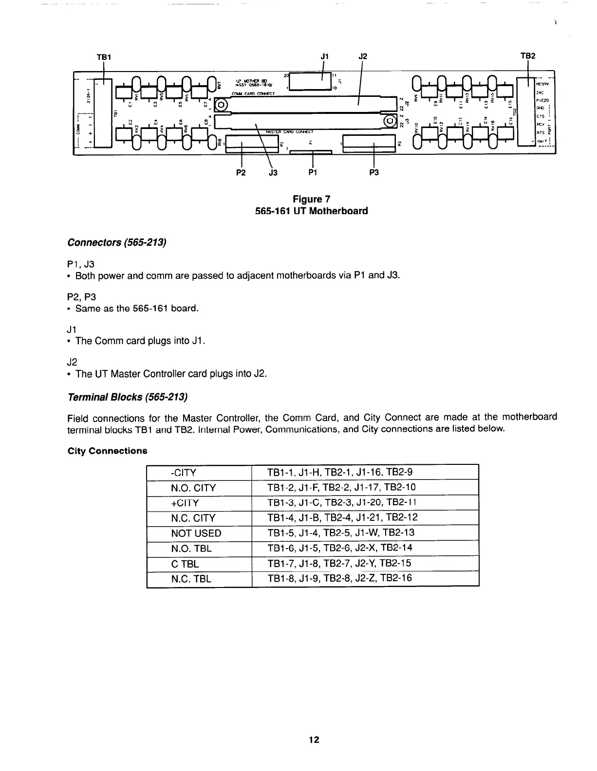
EasyManuals Logo

Simplex 4100+ Service Instructions

Simplex 4100+
98 pages
To Next Page IconTo Next Page
To Previous Page IconTo Previous Page
Page #22 background imageLoading...
Page #22 background image
TBl
Jl 52
TB2
Pi
j3
Figure 7
565-l 61 UT Motherboard
Connectors (565-213)
Pl, J3
l
Both power and comm are passed to adjacent motherboards via Pl and J3.
P2, P3
l
Same as the 565-161 board.
Jl
. The Comm card plugs into Jl .
J2
l
The UT Master Controller card plugs into J2.
Terminal Blocks (565-213)
Field connections for the Master Controller, the Comm Card, and City Connect are made at the motherboard
terminal blocks TBl and TB2. Internal Power, Communications, and City connections are listed below.
City Connections
-CITY
TBl-1, Jl-H, TB2-1, Jl-16, TB2-9
N.O. CITY
TBl-2, Jl -F, TB2-2, Jl-17, TB2-10
+CITY
TBl-3, Jl-C, TB2-3, Jl-20, TB2-11
N.C. CITY
TBl-4, Jl -B, TB2-4, Jl-21, TB2-12
NOT USED
TBl -5, Jl -4, TB2-5, Jl -W, TB2-13
N.O. TBL
TBl-6, Jl-5, TB2-6, J2-X, TB2-14
C TBL
TBl-7, Jl-8, TB2-7, J2-Y, TB2-15
N.C. TBL
TBl-8, Jl-9, TB2-8, J2-Z, TB2-16
12
firealarmresources.com

Table of Contents

Other manuals for Simplex 4100+

Questions and Answers:

Question and Answer IconNeed help?

Do you have a question about the Simplex 4100+ and is the answer not in the manual?

Simplex 4100+ Specifications

General IconGeneral
TypeAddressable Fire Alarm Control Panel
SLC LoopsUp to 10
Operating Temperature32°F to 120°F (0°C to 49°C)
Humidity Range10% to 93% non-condensing
DisplayLCD
CommunicationEthernet
Power Supply120/240 VAC, 50/60 Hz
Battery Backup24 VDC
NAC OutputsExpandable
Releasing CapabilityYes, with releasing modules
Max Notification Appliance Circuits (NACs)Varies by modules
Max Releasing Circuits10
Communication PortsEthernet
Max Devices3, 000

Related product manuals