EasyManuals Logo

Simplex 4100+ Service Instructions

Simplex 4100+
98 pages
To Next Page IconTo Next Page
To Previous Page IconTo Previous Page
Page #91 background imageLoading...
Page #91 background image
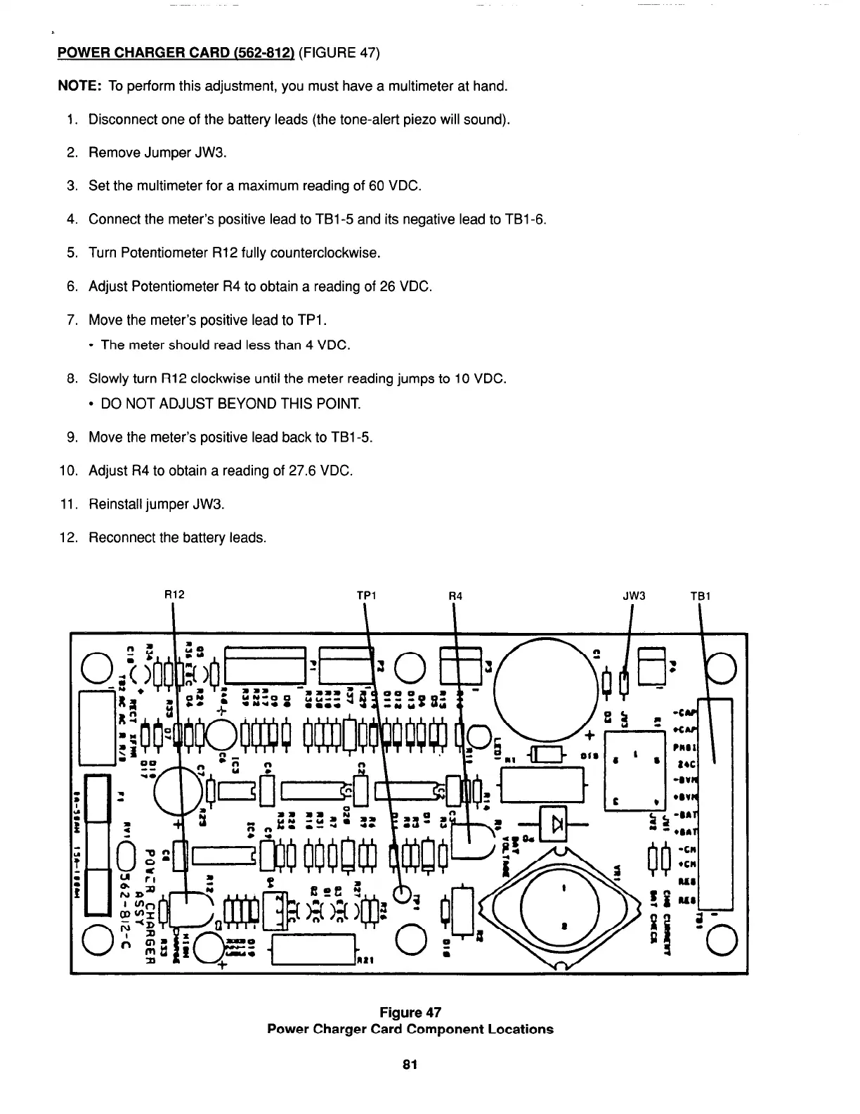
POWER CHARGER CARD (562-812)
(FIGURE 47)
NOTE:
To perform this adjustment, you must have a multimeter at hand.
1. Disconnect one of the battery leads (the tone-alert piezo will sound).
2. Remove Jumper JW3.
3. Set the multimeter for a maximum reading of 60 VDC.
4. Connect the meters positive lead to TBl-5 and its negative lead to TBl-6.
5. Turn Potentiometer R12 fully counterclockwise.
6. Adjust Potentiometer R4 to obtain a reading of 26 VDC.
7. Move the meters positive lead to TPl .
l
The meter should read less than 4 VDC.
8. Slowly turn R12 clockwise until the meter reading jumps to 10 VDC.
l
DO NOT ADJUST BEYOND THIS POINT.
9. Move the meters positive lead back to TBl-5.
10. Adjust R4 to obtain a reading of 27.6 VDC.
11. Reinstall jumper JW3.
12. Reconnect the battery leads.
R12
TPl
R4 JW3
TBl
Figure 47
Power Charger Card Component Locations
81
firealarmresources.com

Table of Contents

Other manuals for Simplex 4100+

Questions and Answers:

Question and Answer IconNeed help?

Do you have a question about the Simplex 4100+ and is the answer not in the manual?

Simplex 4100+ Specifications

General IconGeneral
TypeAddressable Fire Alarm Control Panel
SLC LoopsUp to 10
Operating Temperature32°F to 120°F (0°C to 49°C)
Humidity Range10% to 93% non-condensing
DisplayLCD
CommunicationEthernet
Power Supply120/240 VAC, 50/60 Hz
Battery Backup24 VDC
NAC OutputsExpandable
Releasing CapabilityYes, with releasing modules
Max Notification Appliance Circuits (NACs)Varies by modules
Max Releasing Circuits10
Communication PortsEthernet
Max Devices3, 000

Related product manuals