In addition to the above, the Master Power Supply can connect to:
l
A system current meter
l
A system voltage meter
l
A battery charging current meter
l
A battery voltage meter.
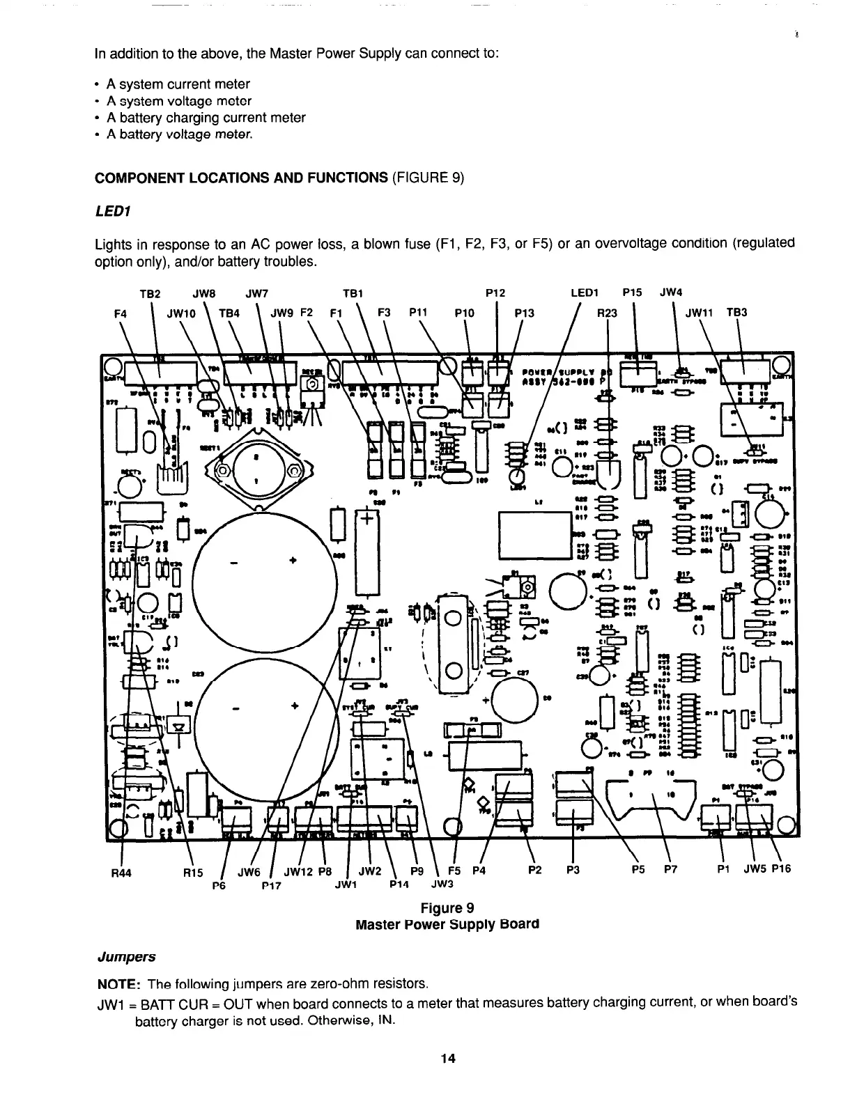
COMPONENT LOCATIONS AND FUNCTIONS
(FIGURE 9)
LED1
Lights in response to an AC power loss, a blown fuse (Fl, F2, F3, or F5) or an overvoltage condition (regulated
option only), and/or battery troubles.
TB2 JW8 JW7
TBl
P12
LED1 P15 JW4
FA \ .IWlll \ TRA
\ .IWQ F2
Fl
\ F3
Pll
Plrl
I
PlR
/ R7R 1
R;5 JVi6 / J&2 +8
1 JiJ2 \ 69 \ F-5
J&5 Pi6
P6
P17
JWl
P14
JW3
Figure 9
Master Power Supply Board
Jumpers
NOTE:
The following jumpers are zero-ohm resistors.
JWl = BATT CUR = OUT when board connects to a meter that measures battery charging current, or when board’s
battery charger is not used. Otherwise, IN.
14