TBl
Jl
J2
TB2
P2
Pl
P3
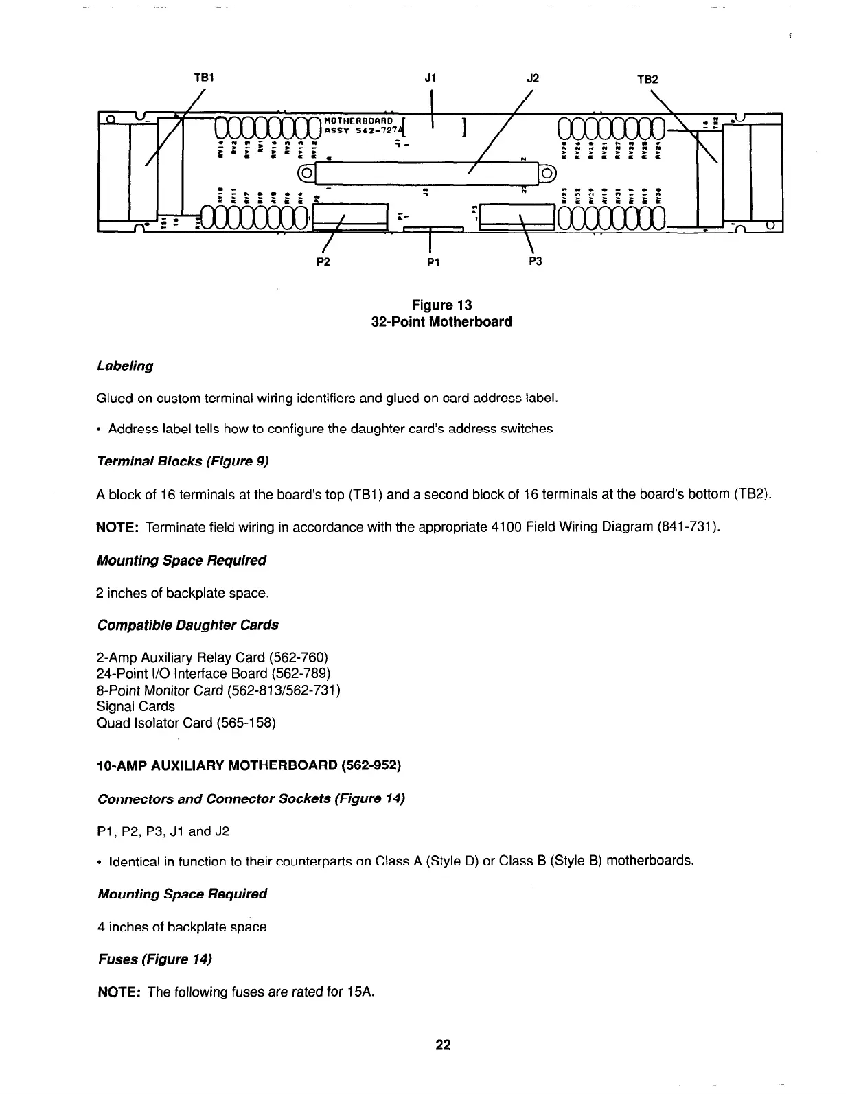
Figure 13
32-Point Motherboard
Labeling
Glued-on custom terminal wiring identifiers and glued-on card address label.
l
Address label tells how to configure the daughter card’s address switches.
Terminal Blocks (Figure 9)
A block of 16 terminals at the board’s top (TBI) and a second block of 16 terminals at the board’s bottom (TB2).
NOTE:
Terminate field wiring in accordance with the appropriate 4100 Field Wiring Diagram (841-731).
Mounting Space Required
2 inches of backplate space.
Compatible Daughter Cards
2-Amp Auxiliary Relay Card (562-760)
24-Point I/O Interface Board (562-789)
8-Point Monitor Card (562-813/562-731)
Signal Cards
Quad Isolator Card (565-l 58)
lo-AMP AUXILIARY MOTHERBOARD (562-952)
Connectors and Connector Sockets (Figure 14)
Pl, P2, P3, Jl and J2
l
Identical in function to their counterparts on Class A (Style D) or Class B (Style 8) motherboards.
Mounting Space Required
4 inches of backplate space
Fuses (Figure 14)
NOTE:
The following fuses are rated for 15A.
22