EasyManuals Logo

Simplex 4100+ Service Instructions

Simplex 4100+
98 pages
To Next Page IconTo Next Page
To Previous Page IconTo Previous Page
Page #19 background imageLoading...
Page #19 background image
i-
MASTER MOTHERBOARD ASSEMBLY
Provides field termination points for the 15 circuits that make up a basic 4100 Fire Alarm System.
Board Identification
Four types of master motherboards are available, each of which can be identified by the name and number it bears.
They are:
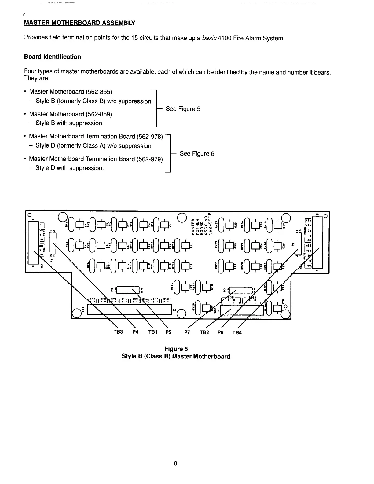
Master Motherboard (562-855)
- Style B (formerly Class B) w/o suppression
1
Master Motherboard (562-859)
t
See Figure 5
- Style B with suppression
A
Master Motherboard Termination Board (562-978)
- Style D (formerly Class A) w/o suppression
1
Master Motherboard Termination Board (562-979)
- Style D with suppression.
See Figure 6
TB3 P4
TBl P5 P7
TB2 P6
TB4
Figure 5
Style B (Class B) Master Motherboard
9
firealarmresources.com

Table of Contents

Other manuals for Simplex 4100+

Questions and Answers:

Question and Answer IconNeed help?

Do you have a question about the Simplex 4100+ and is the answer not in the manual?

Simplex 4100+ Specifications

General IconGeneral
TypeAddressable Fire Alarm Control Panel
SLC LoopsUp to 10
Operating Temperature32°F to 120°F (0°C to 49°C)
Humidity Range10% to 93% non-condensing
DisplayLCD
CommunicationEthernet
Power Supply120/240 VAC, 50/60 Hz
Battery Backup24 VDC
NAC OutputsExpandable
Releasing CapabilityYes, with releasing modules
Max Notification Appliance Circuits (NACs)Varies by modules
Max Releasing Circuits10
Communication PortsEthernet
Max Devices3, 000

Related product manuals