EasyManuals Logo

Simplex 4100+ Service Instructions

Simplex 4100+
98 pages
To Next Page IconTo Next Page
To Previous Page IconTo Previous Page
Page #90 background imageLoading...
Page #90 background image
BATTERY CHARGER ADJUSTMENT
(FIGURE 46)
1.
Disconnect the battery leads from the battery terminals (the tone-alert piezo will sound).
2.
Set the multimeter on the 60 VDC scale. Then, connect the meters negative and positive leads to the black and
red battery leads respectively.
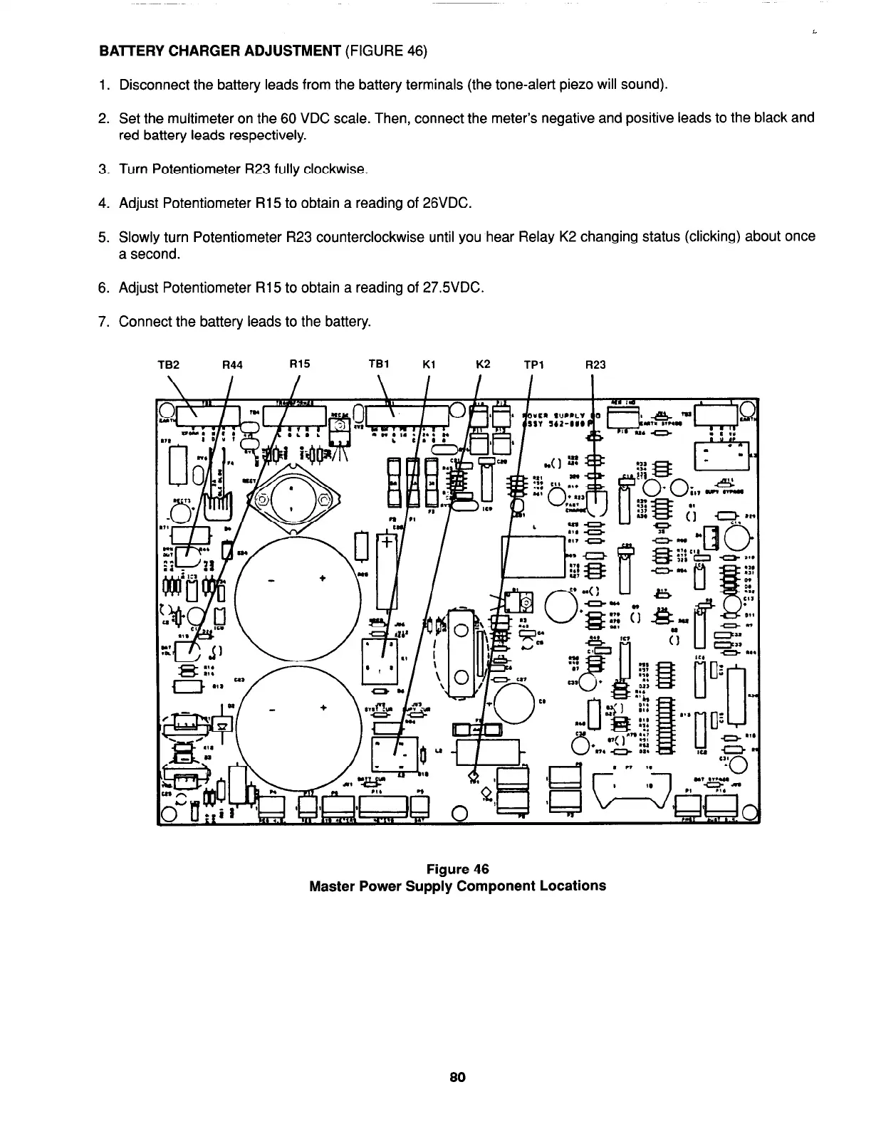
3. Turn Potentiometer R23 fully clockwise.
4. Adjust Potentiometer R15 to obtain a reading of 26VDC.
5. Slowly turn Potentiometer R23 counterclockwise until you hear Relay K2 changing status (clicking) about once
a second.
6. Adjust Potentiometer R15 to obtain a reading of 27.5VDC.
7. Connect the battery leads to the battery.
TB2 R44
TBl
Kl
K2
TPl
R23
Figure 46
Master Power Supply Component Locations
80
firealarmresources.com

Table of Contents

Other manuals for Simplex 4100+

Questions and Answers:

Question and Answer IconNeed help?

Do you have a question about the Simplex 4100+ and is the answer not in the manual?

Simplex 4100+ Specifications

General IconGeneral
TypeAddressable Fire Alarm Control Panel
SLC LoopsUp to 10
Operating Temperature32°F to 120°F (0°C to 49°C)
Humidity Range10% to 93% non-condensing
DisplayLCD
CommunicationEthernet
Power Supply120/240 VAC, 50/60 Hz
Battery Backup24 VDC
NAC OutputsExpandable
Releasing CapabilityYes, with releasing modules
Max Notification Appliance Circuits (NACs)Varies by modules
Max Releasing Circuits10
Communication PortsEthernet
Max Devices3, 000

Related product manuals