P2
P3
Pl
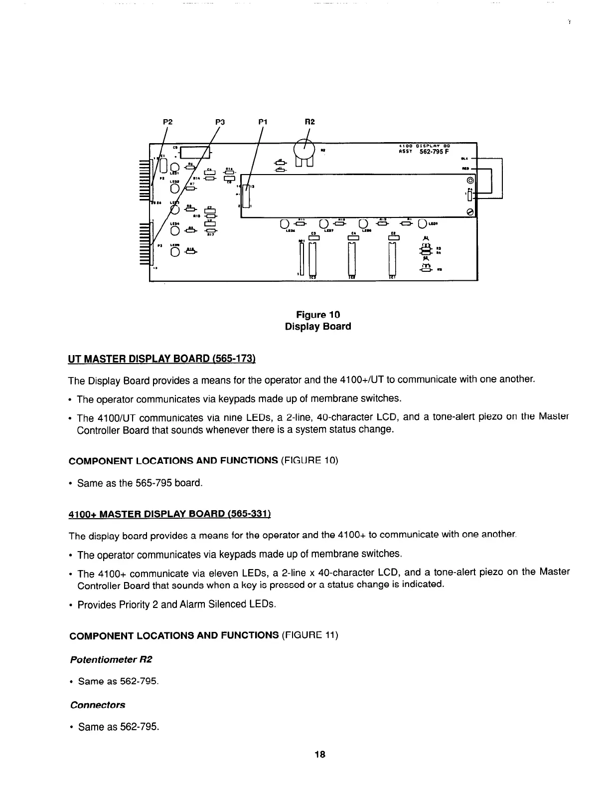
Figure 10
Display Board
UT MASTER DISPLAY BOARD (565-l 73)
The Display Board provides a means for the operator and the 41 OO+/UT to communicate with one another.
l
The operator communicates via keypads made up of membrane switches.
.
The 4100/UT communicates via nine LEDs, a 2-line, 40-character LCD, and a tone-alert piezo on the Master
Controller Board that sounds whenever there is a system status change.
COMPONENT LOCATIONS AND FUNCTIONS
(FIGURE 10)
l
Same as the 565-795 board.
4100+ MASTER DISPLAY BOARD (565-331)
The display board provides a means for the operator and the 4100+ to communicate with one another.
l
The operator communicates via keypads made up of membrane switches.
l
The 4100+ communicate via eleven LEDs, a 2-line x 40-character LCD, and a tone-alert piezo on the Master
Controller Board that sounds when a key is pressed or a status change is indicated.
l
Provides Priority 2 and Alarm Silenced LEDs.
COMPONENT LOCATIONS AND FUNCTIONS
(FIGURE 11)
Potentiometer R2
l
Same as 562-795.
Connectors
l
Same as 562-795.
18