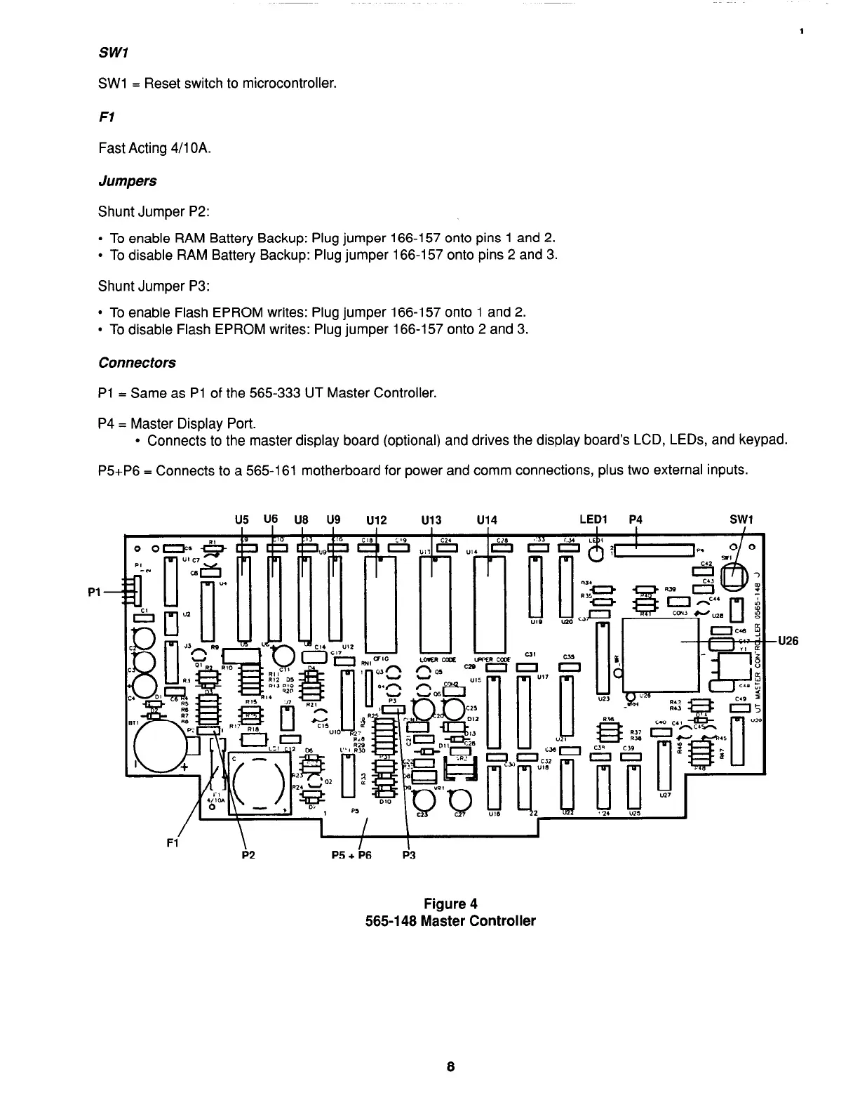
EasyManuals Logo

Simplex 4100+ Service Instructions

Simplex 4100+
98 pages
To Next Page IconTo Next Page
To Previous Page IconTo Previous Page
Page #18 background imageLoading...
Page #18 background image
SW1
SW1 = Reset switch to microcontroller.
Fl
Fast Acting 4/l OA.
Jumpers
Shunt Jumper P2:
l
To enable RAM Battery Backup: Plug jumper 166-l 57 onto pins 1 and 2.
l
To disable RAM Battery Backup: Plug jumper 166-I 57 onto pins 2 and 3.
Shunt Jumper P3:
l
To enable Flash EPROM writes: Plug jumper 166-157 onto 1 and 2.
l
To disable Flash EPROM writes: Plug jumper 166-l 57 onto 2 and 3.
Connectors
Pl = Same as Pl of the 565-333 UT Master Controller.
P4 = Master Display Port.
l
Connects to the master display board (optional) and drives the display boards LCD, LEDs, and keypad.
P5+P6 = Connects to a 565-l 61 motherboard for power and comm connections, plus two external inputs.
U5 U6 U8 U9
u12 u13
u14
LED1 P4
SW1
Pl
Figure 4
565-l 48 Master Controller
-U26
firealarmresources.com

Table of Contents

Other manuals for Simplex 4100+

Questions and Answers:

Question and Answer IconNeed help?

Do you have a question about the Simplex 4100+ and is the answer not in the manual?

Simplex 4100+ Specifications

General IconGeneral
TypeAddressable Fire Alarm Control Panel
SLC LoopsUp to 10
Operating Temperature32°F to 120°F (0°C to 49°C)
Humidity Range10% to 93% non-condensing
DisplayLCD
CommunicationEthernet
Power Supply120/240 VAC, 50/60 Hz
Battery Backup24 VDC
NAC OutputsExpandable
Releasing CapabilityYes, with releasing modules
Max Notification Appliance Circuits (NACs)Varies by modules
Max Releasing Circuits10
Communication PortsEthernet
Max Devices3, 000

Related product manuals