Fl = Between TBl-6 and Kl Center Strap
F2 = Between TBl -3 and Kl Center Strap
F3 = Between TB2-6 and Kl Center Strap
F4 = Between TB2-3 and Kl Center Strap
F5 = Between TB3-3 and Kl Center Strap
F6 = Between TB3-6 and Kl Center Strap
F7 = Between TB4-3 and Ki Center Strap
F8 = Between TB4-6 and Kl Center Strap
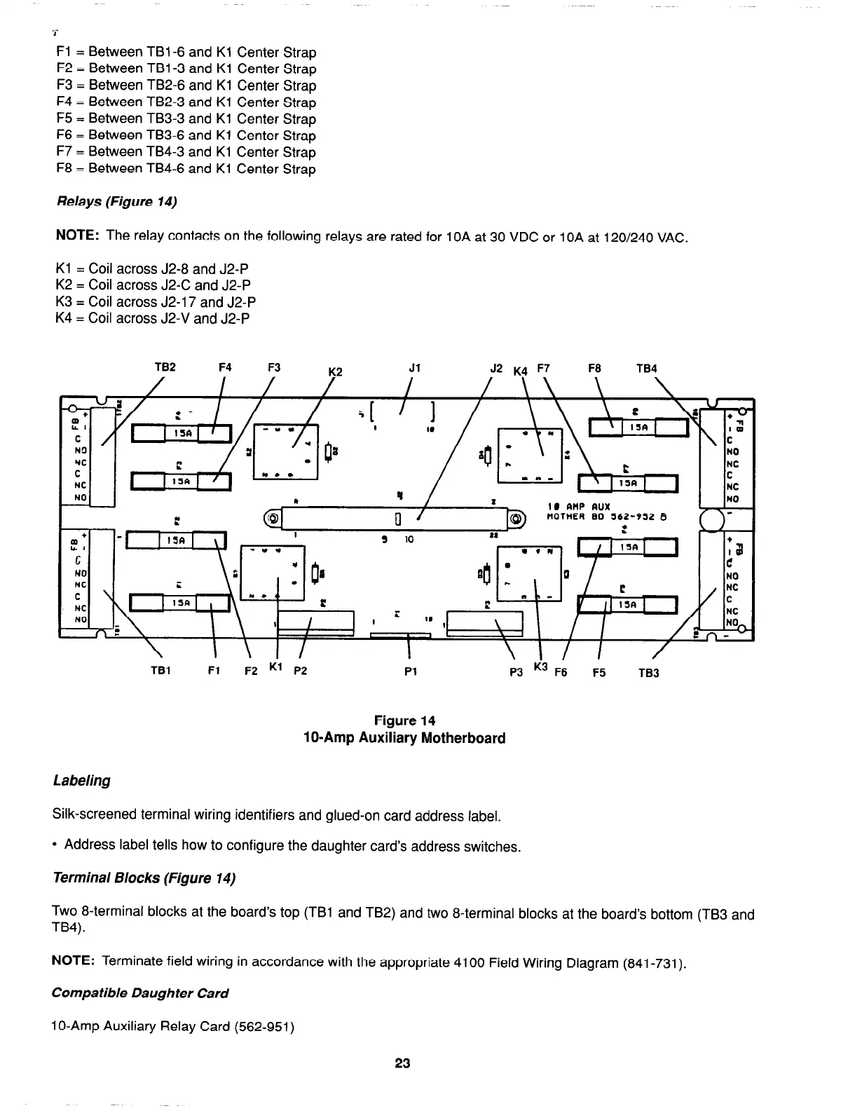
Relays (Figure 14)
NOTE:
The relay contacts on the following relays are rated for 1 OA at 30 VDC or 1 OA at 120/240 VAC.
Kl = Coil across J2-8 and J2-P
K2 = Coil across J2-C and J2-P
K3 = Coil across J2-17 and J2-P
K4 = Coil across J2-V and J2-P
TB2 F4
F3
K2
Jl J2 K4 F7
F8
TB4
IO AMP aux
tlOtHER 80 562-952 8
\ I \I/
I
’
/
TBl
Fl
F2 K1 P2 Pl
F5
TB3
Figure 14
lo-Amp Auxiliary Motherboard
Labeling
Silk-screened terminal wiring identifiers and glued-on card address label.
l
Address label tells how to configure the daughter card’s address switches.
Terminal Blocks (Figure 14)
Two 8-terminal blocks at the board’s top (TBI and TB2) and two 8-terminal blocks at the board’s bottom (TB3 and
TB4).
NOTE:
Terminate field wiring in accordance with the appropriate 4100 Field Wiring Diagram (841-731).
Compatible Daughter Card
1 O-Amp Auxiliary Relay Card (562-951)
23