Internal Power and Communications
1 TXD (Serial Communications Transmit
1 PI -1, P2-1, P2-5, JI-10, J2-10, J3-1
COMMON (Serial Communications Common)
RCV (Serial communications receive)
Pl-2, P2-2, P2-6, Jl -L, J2-L, J3-2
Pl-3, P2-3, P2-7, Jl-11 , J2-11, J3-3
CODE (coded signal bus line)
8C (8-volt common, OV)
+8V (+8-volt system power)
24C (24-volt common, OV)
+24V (+24-volt system power)
PI -4, P2-4, P2-8, Jl -M, J2-M, J3-4
Pl-5, Pl-6, P3-1 ,P3-5, JI-12, J3-6, J2-12, J3-5
PI-7, P3-2, P3-6, Jl-N, J2-N, J3-7
PI -8, PI -9, P3-3, P3-7, Jl-13, J3-9, J2-13, J3-8
Pl-10, P3-4, P3-8, Jl-P, J2-P, J3-10
P4
Local Energy P4-2, -5, -7, -9, -12, -13
Reverse Polarity P4-1, -3, -7, -8, -12
Shunt P4-1, -5, -13
I Radio
[ P4-4, -6, -13
I
Form C
j P4-13
P4
/
- \ ‘1
1 1
1
4 ““V”“VV
\ I
ti2
j2 til
P3
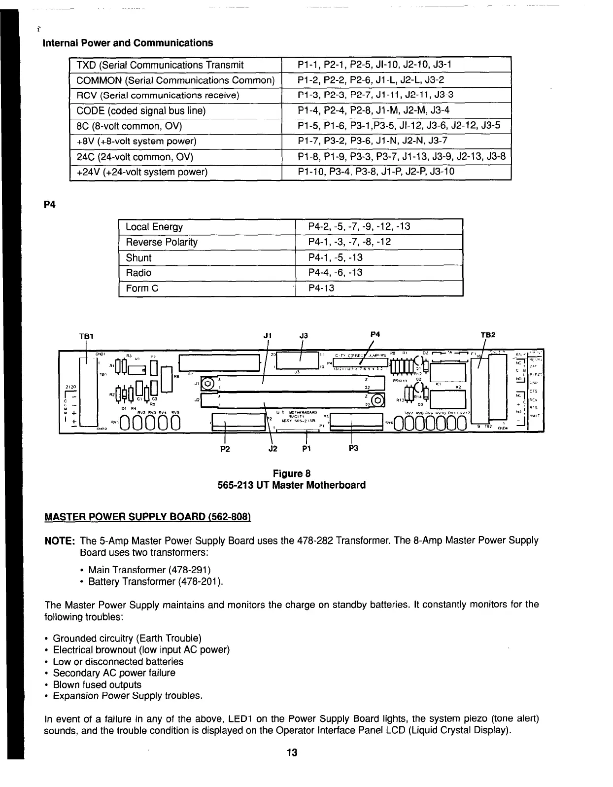
Figure 8
565-213 UT Master Motherboard
MASTER POWER SUPPLY BOARD (562-808)
NOTE:
The 5-Amp Master Power Supply Board uses the 478-282 Transformer. The 8-Amp Master Power Supply
Board uses two transformers:
l
Main Transformer (478-291)
l
Battery Transformer (478-201).
The Master Power Supply maintains and monitors the charge on standby batteries. It constantly monitors for the
following troubles:
l
Grounded circuitry (Earth Trouble)
l
Electrical brownout (low input AC power)
l
Low or disconnected batteries
l
Secondary AC power failure
l
Blown fused outputs
l
Expansion Power Supply troubles.
In event of a failure in any of the above, LED1 on the Power Supply Board lights, the system piezo (tone alert)
sounds, and the trouble condition is displayed on the Operator Interface Panel LCD (Liquid Crystal Display).
13