c
The primary and secondary leads of the output transformer are connected to their respective positions on terminal
block TB3, located on the 100 Watt Amplifier board.
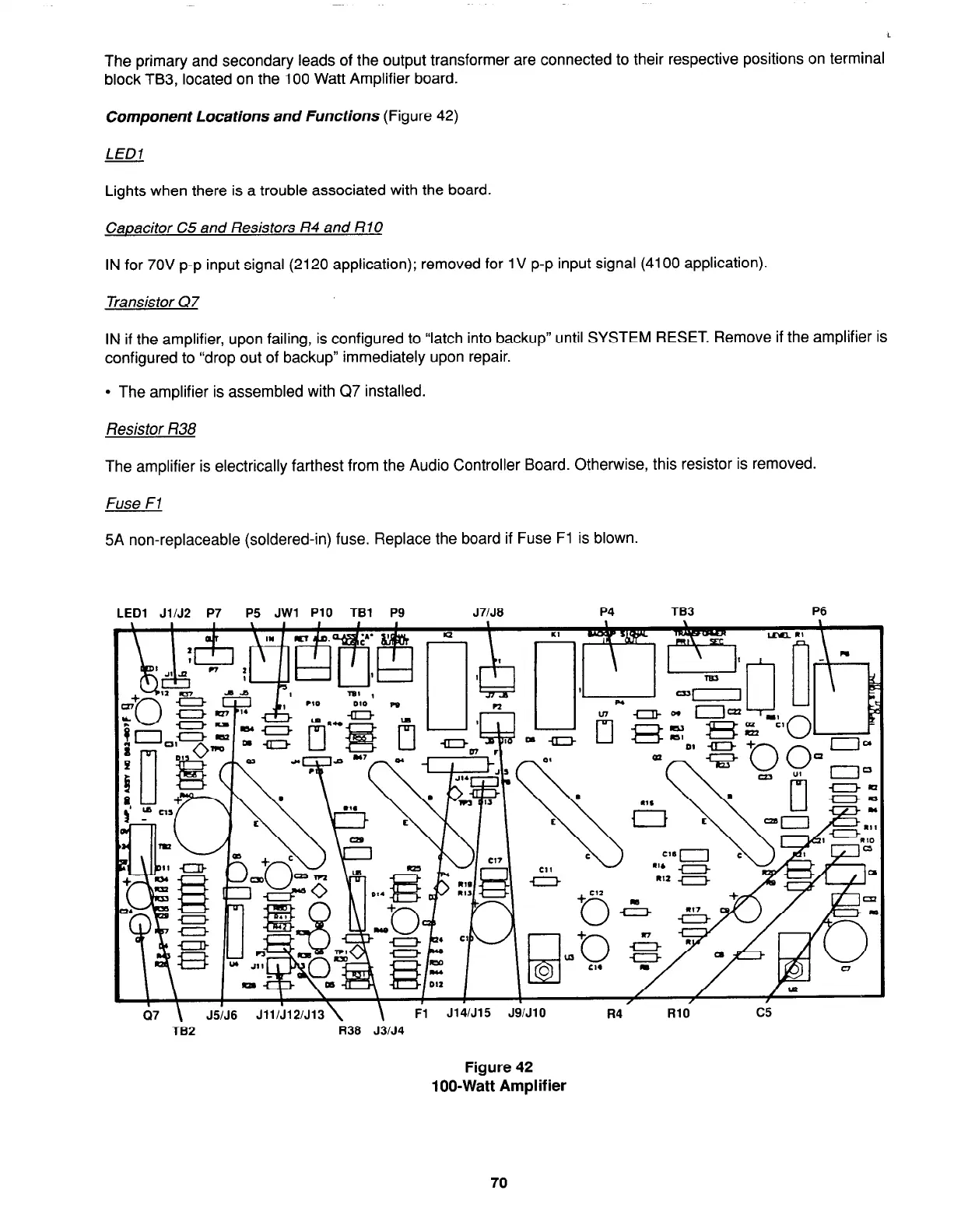
Component Locations and Functions (Figure 42)
LED1
Lights when there is a trouble associated with the board.
Capacitor C5 and Resistors R4 and RlO
IN for 70V p-p input signal (2120 application); removed for 1 V p-p input signal (4100 application).
Transistor Q7
IN if the amplifier, upon failing, is configured to “latch into backup” until SYSTEM RESET. Remove if the amplifier is
configured to “drop out of backup” immediately upon repair.
l
The amplifier is assembled with Q7 installed.
Resistor R38
The amplifier is electrically farthest from the Audio Controller Board. Otherwise, this resistor is removed.
Fuse F7
5A non-replaceable (soldered-in) fuse. Replace the board if Fuse Fl is blown.
LED1 JllJ2 P7 P5 JWl PlO TBl P9
J7/J8
P4 TB3 P6
+
Cl2
0
H
+
la
0
0
CM
- -.-
I
/
/
/ul
iI7 \
J5;J6 Jll/i12/J13\
\
/
/
I
Fl J14/J15 JSIJlO
R4
RlO
c5
TB2
R38 J3lJ4
Figure 42
loo-Watt Amplifier
70