Component Locations and Functions (Figure 21)
LED1
Lights when there is a trouble associated with the board.
IC7 and IC9
The 246-401 masked chips contain the card’s program.
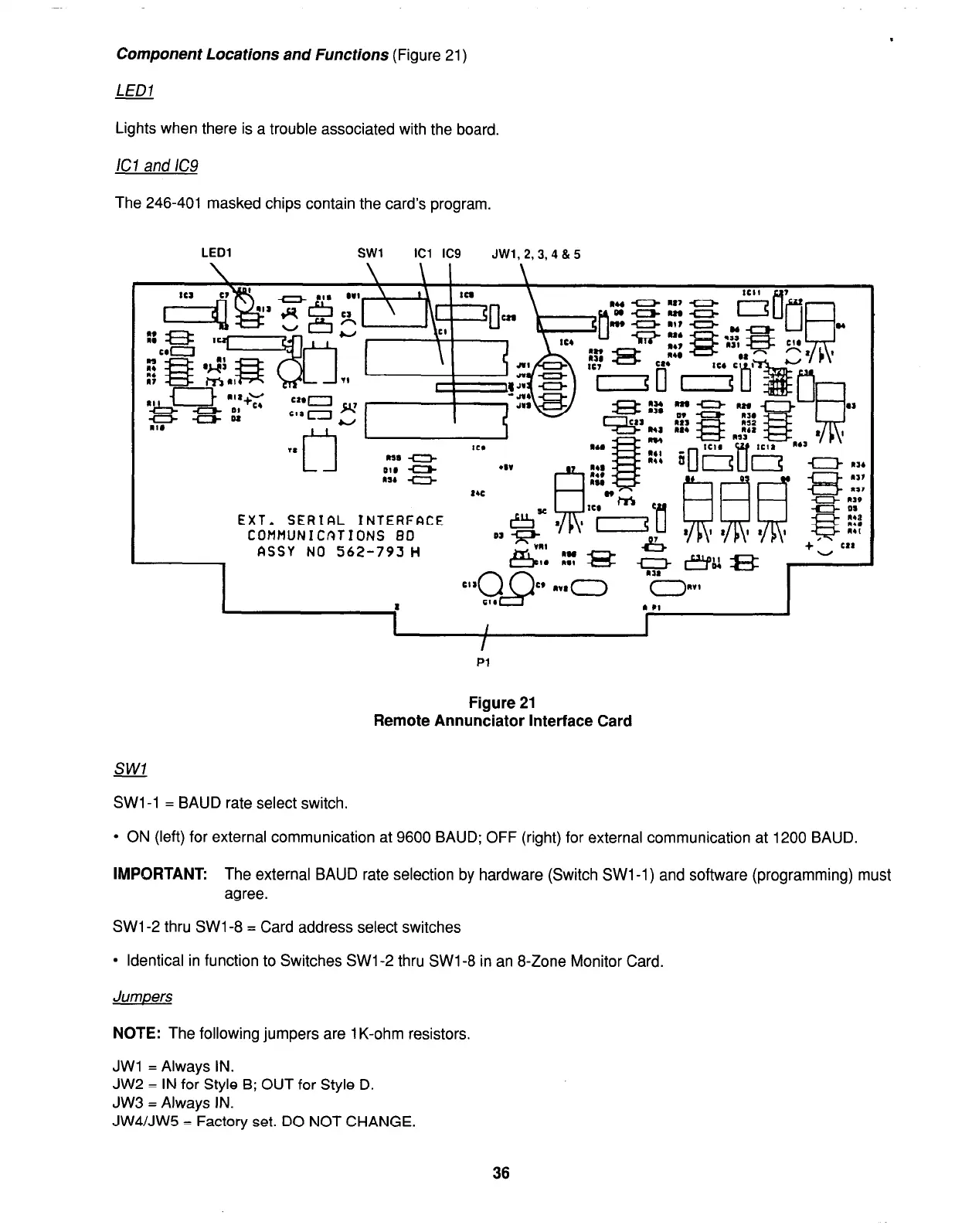
LED1
SW1
ICl IC9
JWl.2,3.4&5
EXT. SERIAL INTERFACE
COMMUNICATIONS 80
ASSY NO 562-793H
I
I
I
Pl
Figure 21
Remote Annunciator Interface Card
SW1 -1 = BAUD rate select switch.
l
ON (left) for external communication at 9600 BAUD; OFF (right) for external communication at 1200 BAUD.
IMPORTANT:
The external BAUD rate selection by hardware (Switch SW1 -1) and software (programming) must
agree.
SW1 -2 thru SW1 -8 = Card address select switches
l
Identical in function to Switches SW1 -2 thru SW1 -8 in an 8-Zone Monitor Card.
Jumpers
NOTE:
The following jumpers are 1 K-ohm resistors.
JWl = Always IN.
JW2 = IN for Style B; OUT for Style D.
JW3 = Always IN.
JW4/JW5 = Factory set. DO NOT CHANGE.
36