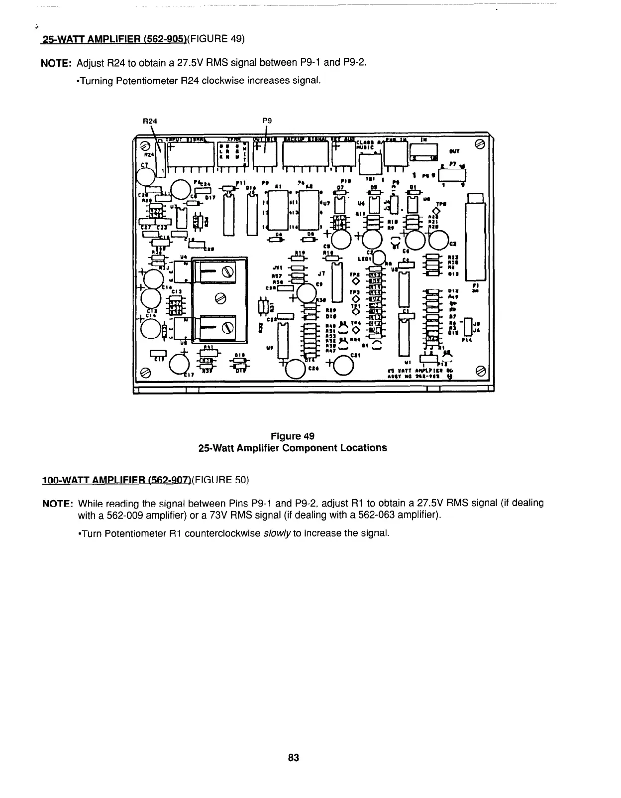
25WATT AMPLIFIER
(562-905j(FIGURE 49)
NOTE:
Adjust R24 to obtain a 27.5V RMS signal between P9-1 and P9-2.
*Turning Potentiometer R24 clockwise increases signal.
R24
P9
Figure 49
25-Watt Amplifier Component Locations
loo-WATT AMPLIFIER
(562-907)(FIGURE 50)
NOTE:
While reading the signal between Pins P9-1 and P9-2, adjust Rl to obtain a 27.5V RMS signal (if dealing
with a 562-009 amplifier) or a 73V RMS signal (if dealing with a 562-063 amplifier).
*Turn Potentiometer Rl counterclockwise slow/y to increase the signal.
83