fB3 ti4
Ti31 I%
TEi5 P7
TB2 P6
TB4
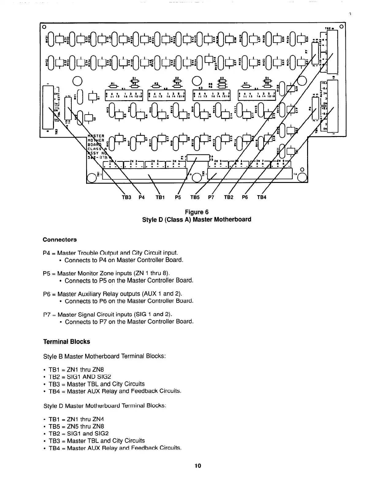
Figure 6
Style D (Class A) Master Motherboard
Connectors
P4 = Master Trouble Output and City Circuit input.
l
Connects to P4 on Master Controller Board
P5 = Master Monitor Zone inputs (ZN 1 thru 8).
l
Connects to P5 on the Master Controller Board.
P6 = Master Auxiliary Relay outputs (AUX 1 and 2).
l
Connects to P6 on the Master Controller Board.
P7 = Master Signal Circuit inputs (SIG 1 and 2).
l
Connects to P7 on the Master Controller Board.
Terminal Blocks
Style B Master Motherboard Terminal Blocks:
l
TBl = ZNl thru ZN8
l
TB2 = SIG1 AND SIG2
l
TB3 = Master TBL and City Circuits
l
TB4 = Master AUX Relay and Feedback Circuits.
Style D Master Motherboard Terminal Blocks:
l
TBl = ZNl thru ZN4
l
TB5 = ZN5 thru ZN8
l
TB2 = SIG1 and SIG2
l
TB3 = Master TBL and City Circuits
l
TB4 = Master AUX Relay and Feedback Circuits.
10