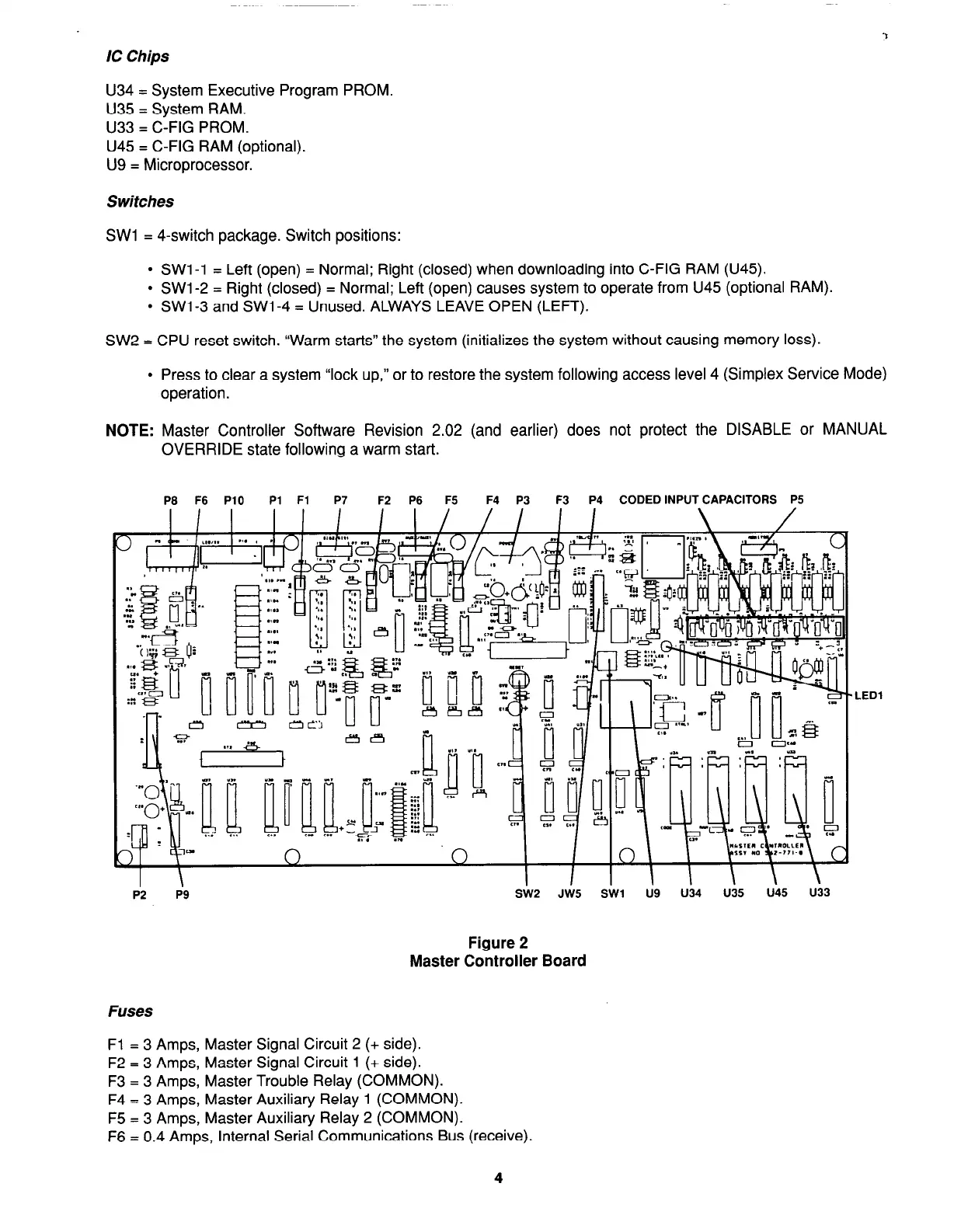
IC Chips
U34 = System Executive Program PROM.
U35 = System RAM.
U33 = C-FIG PROM.
U45 = C-FIG RAM (optional).
U9 = Microprocessor.
Switches
SW1 = 4-switch package. Switch positions:
l
SW1 -1 = Left (open) = Normal; Right (closed) when downloading into C-FIG RAM (U45).
l
SW1 -2 = Right (closed) = Normal; Left (open) causes system to operate from U45 (optional RAM).
l
SW1 -3 and SW1 -4 = Unused. ALWAYS LEAVE OPEN (LEFT).
SW2 = CPU reset switch. “Warm starts” the system (initializes the system without causing memory loss).
l
Press to clear a system “lock up,” or to restore the system following access level 4 (Simplex Service Mode)
operation.
NOTE:
Master Controller Software Revision 2.02 (and earlier) does not protect the DISABLE or MANUAL
OVERRIDE state following a warm start.
P8 F6 PlO Pi Fl P7 F2 P6 F5 F4 P3 F3 P4 CODED INPUT CAPACITORS P5
I I I /
I I
I
\ 1
I I / \ I Ud.l.6
I.. .nC.‘u I T\ , I
I \
P2 P9
Figure 2
Master Controller Board
Fuses
LED1
Fl = 3 Amps, Master Signal Circuit 2 (+ side).
F2 = 3 Amps, Master Signal Circuit 1 (+ side).
F3 = 3 Amps, Master Trouble Relay (COMMON).
F4 = 3 Amps, Master Auxiliary Relay 1 (COMMON).
F5 = 3 Amps, Master Auxiliary Relay 2 (COMMON).
F6 = 0.4 Amps, Internal Serial Communications Bus (receive).
4