Identical in function to Switch SW1 in an El-Zone Monitor Card.
JumDers
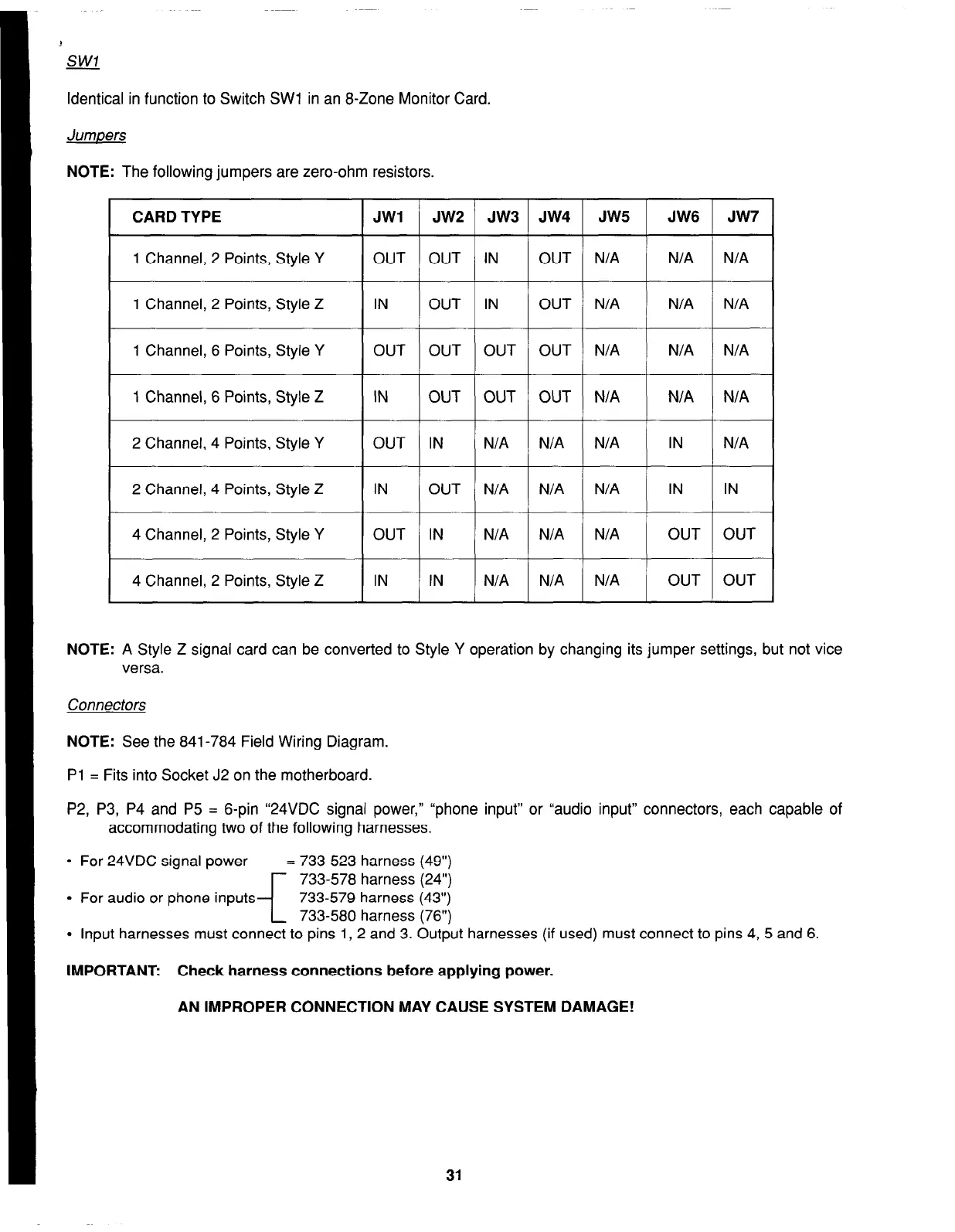
NOTE:
The following jumpers are zero-ohm resistors.
CARD TYPE
JWI
1 Channel, 2 Points, Style Y OUT
1 Channel, 2 Points, Style Z IN
1 Channel, 6 Points, Style Y OUT
1 Channel, 6 Points, Style Z IN
2 Channel, 4 Points, Style Y OUT
2 Channel, 4 Points, Style Z IN
4 Channel, 2 Points, Style Y OUT
4 Channel, 2 Points, Style Z IN
JW2 / JW3
OUT IN
OUT IN
OUT OUT
OUT OUT
IN N/A
OUT N/A
IN N/A
IN N/A
JW4
OUT
OUT
OUT
OUT
N/A
N/A
N/A
N/A
JW5 JW6 JW7
N/A
N/A N/A
N/A N/A N/A
N/A
N/A N/A
“”
N/A 1 OUT 1 OUT 1
NOTE:
A Style Z signal card can be converted to Style Y operation by changing its jumper settings, but not vice
versa.
Connectors
NOTE:
See the 841-784 Field Wiring Diagram.
Pl = Fits into Socket J2 on the motherboard.
P2, P3, P4 and P5 = 6-pin “24VDC signal power,” “phone input” or “audio input” connectors, each capable of
accommodating two of the following harnesses.
l
For 24VDC signal power = 733-523 harness (49”)
733-578 harness (24”)
l
For audio or phone inputs
i
733-579 harness (43”)
733-580 harness (76”)
l
Input harnesses must connect to pins 1, 2 and 3. Output harnesses (if used) must connect to pins 4, 5 and 6.
IMPORTANT: Check harness connections before applying power.
AN IMPROPER CONNECTION MAY CAUSE SYSTEM DAMAGE!
31