,
NOTE:
Switch position SW1 -1 is not used.
SW2 = Active MAPNET@ Device Loops Select Switch.
l
Selecting rotary switch position 1, 2, 3, or 4 selects the corresponding number of active MAPNET@ loops.
NOTE:
Switch positions 0, 5, 6, and 7 are invalid selections.
SW2 LED 1 thru LED 4
Jumpers
JW2, JW3, JW5 = IN.
JWl, JW4,
JW6,
JW7, JW8 = OUT.
Pl
\
\
I
JWl thru JW8
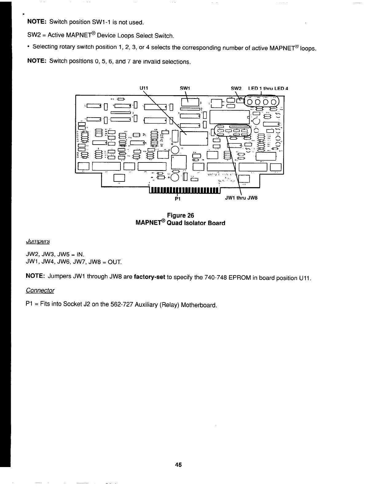
Figure 26
MAPNEF Quad Isolator Board
NOTE:
Jumpers JWl through JW8 are
factory-set
to specify the 740-748 EPROM in board position Ull.
Connector
Pl = Fits into Socket J2 on the 562-727 Auxiliary (Relay) Motherboard.
45