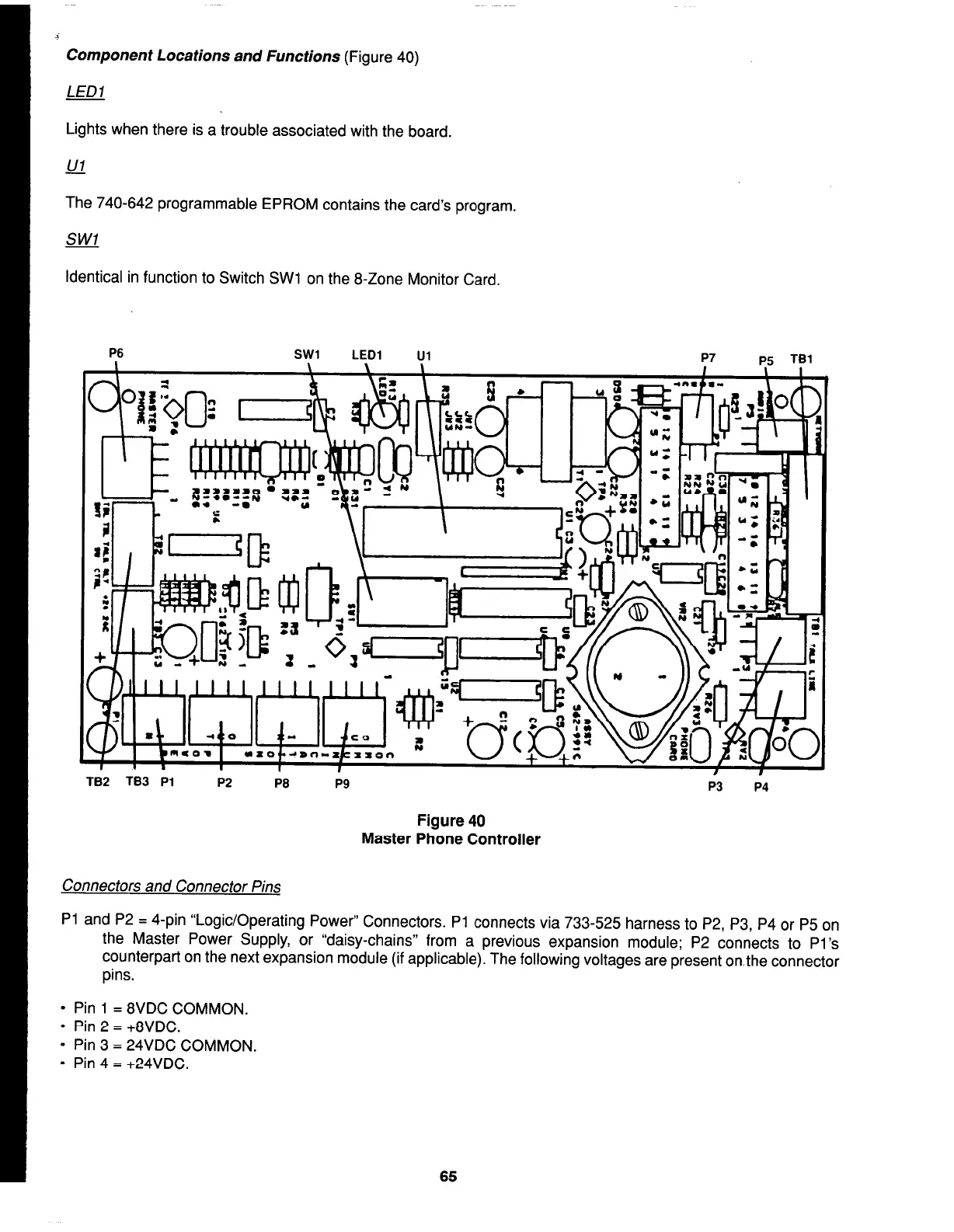
Component Locations and Functions (Figure 40)
LED1
Lights when there is a trouble associated with the board.
The 740-642 programmable EPROM contains the card’s program.
Identical in function to Switch SW1 on the 8-Zone Monitor Card.
P6
TB2 TB3 Pl
P2
P8
P9
Connectors and Connector Pins
P3 P4
Figure 40
Master Phone Controller
Pl and P2 = 4-pin “Logic/Operating Power” Connectors. Pl connects via 733-525 harness to P2, P3, P4 or P5 on
the Master Power Supply, or “daisy-chains” from a previous expansion module; P2 connects to Pi’s
counterpart on the next expansion module (if applicable). The following voltages are present on.the connector
pins.
l
Pin 1 = 8VDC COMMON.
l
Pin 2 = +8VDC.
l
Pin 3 = 24VDC COMMON.
l
Pin 4 = +24VDC.
65