C28
R28
J8 J9
R31 JWl 57
LED1
J3lJ4 JllJ2
ns
J5lJti
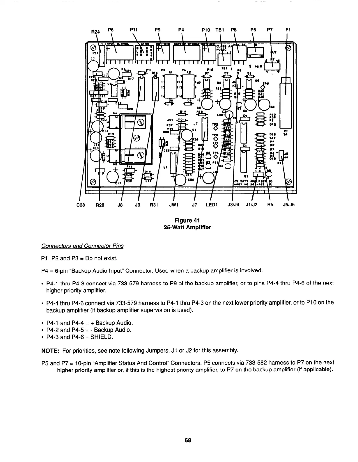
Figure 41
25Watt Amplifier
Connectors and Connector Pins
PI, P2 and P3 = Do not exist.
P4 = 6-pin “Backup Audio Input” Connector. Used when a backup amplifier is involved.
l
P4-1 thru P4-3 connect via 733-579 harness to P9 of the backup amplifier, or to pins P4-4 thru P4-6 of the next
higher priority amplifier.
l
P4-4 thru P4-6 connect via 733-579 harness to P4-1 thru P4-3 on the next lower priority amplifier, or to PI 0 on the
backup amplifier (if backup amplifier supervision is used).
l
P4-1 and P4-4 = + Backup Audio.
l
P4-2 and P4-5 = - Backup Audio.
l
P4-3 and P4-6 = SHIELD.
NOTE:
For priorities, see note following Jumpers, Jl or J2 for this assembly.
P5 and P7 = 1 O-pin “Amplifier Status And Control” Connectors. P5 connects via 733-582 harness to P7 on the next
higher priority amplifier or, if this is the highest priority amplifier, to P7 on the backup amplifier (if applicable).
68