Simrad GC80/85 Double System Controller
48
988-12721-001
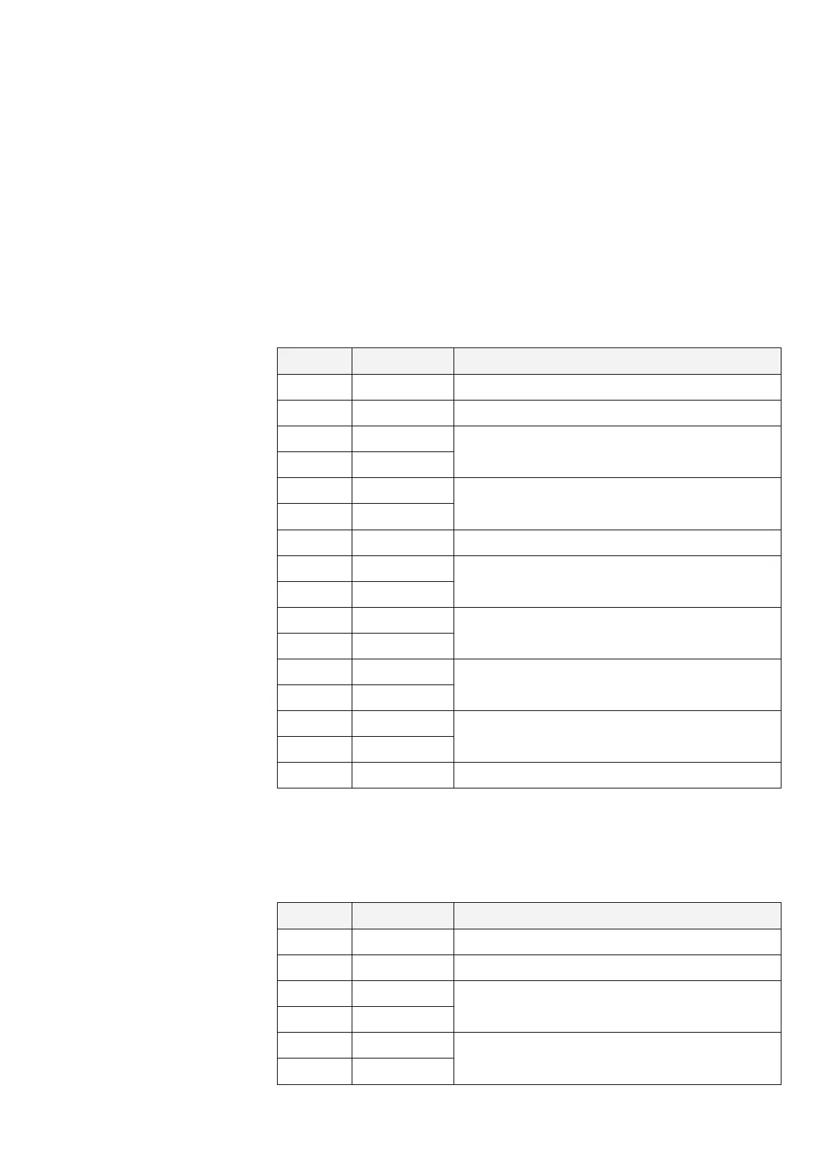
10 TERMINAL LAYOUT
This section includes tables that list all terminal pins and terminal labelling
on the DGCT board in the GC80/85 Double System Controller unit. The
tables include detailed descriptions of each terminal.
10.1 DGCT board
TB1
GYROCOMPASS NO.1
PIN NO NAME DETAILS
1 G1_24V Power supply (24 V DC) (Repeater)
2 G1_GND Power supply (24 V DC GND) (Repeater)
3 G1TX+
Internal communication serial signal output
4 G1TX-
5 G1RX+
Internal communication serial signal input
6 G1RX-
7 G1SC Internal communication serial signal GND
8 G1SEL1
Selection signal input (potential free contact)
9 G1SEL2
10 E1SEL1
External heading selection signal input
(potential free contact)
11 E1SEL2
12 G1ALCN1
Alert signal output (potential free contact)
13 G1ALCN2
14 G1RNCN1
Running signal output (potential free contact)
15 G1RNCN2
16 Not used -
TB2
GYROCOMPASS NO.2
PIN NO NAME DETAILS
1 G2_24V Power supply (24 V DC) (Repeater)
2 G2_GND Power supply (24 V DC GND) (Repeater)
3 G2TX+
Internal communication serial signal output
4 G2TX-
5 G2RX+
Internal communication serial signal input
6 G2RX-