Radar 18
Radar is the Radio Detection And Ranging system. Radar
functions require an optional Simrad radar system to be
installed. Three radar systems are available; 2 kW, 4 kW,
or 6 kW.
When the radar is operating, the scanner transmits
powerful microwave radio pulses which are reected
back from any solid objects such as land masses or other
boats. These objects are called targets and are shown on
the radar window.
The scanner rotates through 360° so the radar window
shows all of the area around your boat within the range
of the scanner, producing a map-like display called the
PPI (Plan Position Indicator).
Typically, your boat is in the center of the radar window
with concentric range rings surrounding it. The range
rings help you to quickly estimate the distance to various
targets.
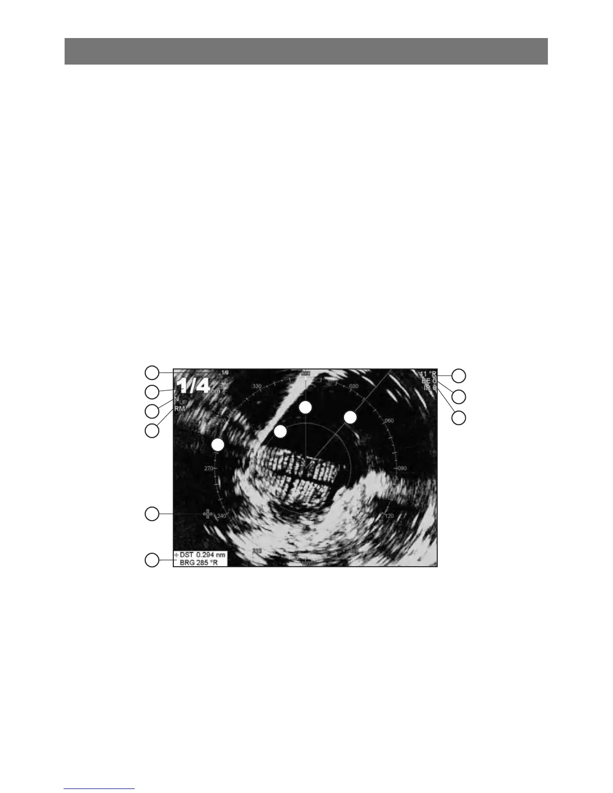
17-1 Radar window
The radar window shows:
A Distance between each range ring (in
this example, 1/8 nautical mile)
B Range of radar (in this example, shown
in large digits)
C Radar rotation (in this example, North
Up)
D Radar motion mode (in this example,
Relative Mode)
E Cursor
F Distance and bearing to the cursor
position
G Compass ring
H Range ring
I North line (blue)
J Heading line (white)
K The bearing (in Relative, True, or
Magnetic mode)
L Echo Expansion setting
M Interference Rejection setting
I
J
H
M
L
K
D
C
B
A
G
E
F