Position Designation Explanation
C MV transformer The MV transformer converts the inverter output voltage to the
voltage level of the medium-voltage grid.
D Medium-voltage switchgear* The medium-voltage switchgear disconnects the MV trans-
former from the medium-voltage grid.
E Communit*
or
Control device for cascade control*
The Communit contains control and communication devices.
The order option "Cascade control" allows for staggered recon-
nection of several medium-voltage switchgears after a grid fail-
ure or maintenance work.
F Transformer for internal power supply* The transformer for internal power supply provides the supply
voltage for the MVPowerStation and its devices. It is con-
nected to the low-voltage side of the MV transformer (see cir-
cuit diagram).
G Station subdistribution The station subdistribution contains fuse and switching elements
for the supply voltage.
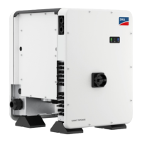
H Sunny Central CP-JP The SunnyCentral is a PV inverter that converts the direct cur-
rent generated in the PV arrays into grid-compliant alternating
current.
* optional
3.3 Design of the inverter
Figure 3: Design of the Inverter
Position Designation
A Inverter cabinet
B Interface cabinet
C Connection area
3 Product Overview
SMA Solar Technology AG
System ManualMVPS22JP-SH-en-1120
 Loading...
