7. Transport the MVPowerStation to its final position as close to the ground as possible.
8. If the MVPowerStation is to be transported directly to the mounting location and installed on the support surface,
attach the support feet (see Section4.6, page43).
9. Set the MVPowerStation down. The support surface must be suitable for the weight of the MVPowerStation in
accordance with the requirements (see "Information on Transport and Mounting of the MVPowerStation").
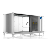
4.4 Transporting the MVPowerStation by Truck, Train and Ship
Requirements:
☐ The means of transport must be equipped with container locks.
☐ The doors of the MVPowerStation must be closed.
☐ The factory-fitted transport lock on the devices of the MVPowerStation must be in place.
☐ If transported by train, the MVPowerStation must be loaded on railroad cars with shock absorbers.
Procedure:
1. Load the MVPowerStation onto the means of transport (see Section4.3, page41).
2. Use container locks to secure the MVPowerStation by at least four upper or lower corner castings.
4.5 Removing the Supplied Mounting Material from the MVPowerStation
Upon delivery, the supplied mounting material is located in the compartment of the medium-voltage switchgear.
Procedure:
1. Temporarily store the MVPowerStation in a suitable location.
2. Open the medium-voltage switchgear compartment (see Section12.1, page159).
3. Set up the medium-voltage switchgear service platform (see Section12.2, page162).
4. Remove the required mounting material from the medium-voltage switchgear compartment (see Section16.1
"Scope of Delivery", page249).
5. Remove the medium-voltage switchgear service platform.
6. Close the medium-voltage switchgear compartment (see Section12.1, page159).
4 Transport and Mounting
SMA Solar Technology AG
System ManualMVPS22JP-SH-en-1142
 Loading...
