4. Remove the foils from the ventilation openings on the doors in the compartment of the medium-voltage switchgear:
• Remove the grids on the inside of the doors.
• Remove the foil from the ventilation openings.
• Mount the grids on the inside of the doors.
5. Remove the other foils from all remaining components.
6. Mount the base plate for the cable entry:
• Disassemble the panels on the base of the medium-voltage switchgear (see Section12.3.2.1, page166).
• Remove the screws of the cover plate under the medium-voltage switchgear.
• Remove the cover plate from the medium-voltage switchgear. The cover plate is no longer needed.
• Fasten the base plate for the cable entry above the opening for the cable entry.
• Mount the panels on the base of the medium-voltage switchgear (see Section12.3.2.1, page166).
7. Flip the working platform of the medium-voltage switchgear and lock it.
8. Close the medium-voltage switchgear compartment (see Section12.1, page159).
5.3.5 Removing the Desiccant Bags
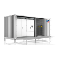
5.3.5.1 Removing the Desiccant Bag from the Station Container
Desiccant bags are included with sea freight orders. The desiccant bags absorb moisture formed during transport.
Procedure:
1. Open the medium-voltage switchgear compartment (see Section12.1, page159).
2. Remove the desiccant bags from the station container. Remove the cable ties around the desiccant bags using
diagonal cutting pliers. The desiccant bags are to be found at the following positions:
• Between the inverters
• In the compartment of the MV transformer
• In the compartment of the medium-voltage switchgear
3. Close the medium-voltage switchgear compartment (see Section12.1, page159).
5.3.5.2 Replacing the Desiccant Bag in the Inverter
Desiccant bag in the inverter cabinet
The desiccant bag in the inverter cabinet protects the electronic components from moisture. The desiccant bag
must be replaced by a new desiccant bag included in the scope of delivery oneday before commissioning.
Procedure:
1. Remove and dispose of the desiccant bag located under the inverter bridges.
2. Remove the desiccant bag included in the scope of delivery from the foil and position it under the inverter bridges.
5.3.6 Connecting the Battery to the Control Device of the Cascade Control
In order option "Cascade control", the battery of type 12V to 24Ah is located in the medium-voltage compartment
included in the scope of delivery for the MVPowerStation. The battery must be connected to the control device.
Do not touch the battery terminals.
The battery for the control device is charged upon delivery.
• When transporting the battery, do not touch the terminals.
5 Installation
SMA Solar Technology AG
System ManualMVPS22JP-SH-en-1156
 Loading...
