90
Scope Multimeter Operation and Controls
Coupling AC
Coupling AC subtracts the average value of a signal so that small variations can be displayed in
the waveform. This is accomplished by blocking the direct current (DC) portions of a signal in
order to amplify (show) the alternating current (AC) portions of the signal, without driving the trace
off of the screen.
Using coupling AC can be helpful when testing and diagnosing alternator ripple or fuel pump
amperage, by allowing you to see any abnormal small variations or events.
To turn coupling AC on and off, select the Coupling AC icon.
Trigger
i The Trigger feature is only available in the lab scope function.
A trigger can be used to stabilize a changing or erratic signal (a signal that may flicker or drift as it
refreshes), so that it is easier to view or diagnose. This stabilization effect is accomplished by
basically displaying the same part of the trace repeatedly from the same starting point, thus the
flicker or drift is minimized which makes the trace appear more consistent or static.
A trigger is basically a “specific point” on the display, at which a trace will start to display (start the
sweep) if it crosses that point.
The trigger feature allows you to set the conditions of that “specific point” also called a “trigger
point”. When the trigger conditions are set, and a trace “meets” those conditions (crosses the
trigger point), the trace will start.
Trigger conditions:
• Vertical scale position (amplitude)
• Sweep position - the horizontal scale position, or position in time
• Slope direction - the direction the trace must be moving (up/rising or positive) or (down/
falling or negative) when crossing the trigger point.
i Triggers can be set on any channel, however only one trigger can be activated (used) at a time.
If a trigger is set outside the range of the scales, a yellow marker (e.g. arrow with plus symbol) will
be displayed (Figure 8-22) indicating the trigger is out of range and a confirmation screen will
display.
When a trigger is set on a channel, and more than one channel is active (displayed), trigger
conditions must be met for that channel in order to display all the other channels.
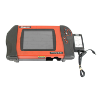
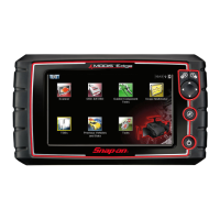
Coupling AC Icons
On (DC signal portion blocked) Off (DC signal portion not blocked)