Do you have a question about the Snap-On Modis Ultra and is the answer not in the manual?
Explains safety message signal words, types, and icons for hazard identification.
Refers to accompanying safety instructions for a complete list of critical safety guidelines.
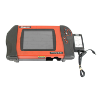
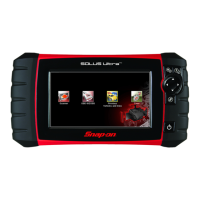
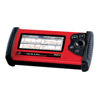
Details the physical components and controls of the diagnostic tool.
Provides detailed technical specifications of the diagnostic tool, including dimensions and power.
Describes the function and operation of the unit's physical control keys.
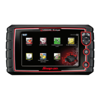
Overview of the main Home screen, its elements like the Title Bar, and status indicators.
Describes the function of each button on the Home screen for accessing tool modules.
Explains the common icons found in the toolbars for navigation and control.
Steps for safely powering down the diagnostic tool, including communication termination.
How to navigate within the Scanner module, including screen layout and toolbar functions.
General navigation for Guided Component Test and Scope Multimeter modules.
Steps for connecting the scan tool to a vehicle using the data cable.
Troubleshooting a 'no communication' error, including common causes and checks.
Overview of the Scanner module's main functions: Scanner and Troubleshooter.
Accessing and viewing diagnostic trouble codes, including display and clearing options.
Erasing diagnostic trouble codes from vehicle memory, with important considerations.
Performing a scan to identify diagnostic issues, including pre/post scan importance.
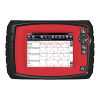
Viewing live datastream parameters from the vehicle ECM in data display mode.
How to pause data collection for closer examination of waveforms and data.
Creating a custom list of parameters for data display to focus on specific data.
Options for changing screen views: PID List, 1 Graph, 2 Graph, and 4 Graph.
How to lock parameters to keep them in place during scrolling for easier monitoring.
Saving datastream values as recorded movies for analysis and documentation.
Configuring the scan tool to automatically capture data when a parameter value crosses a threshold.
Accessing vehicle-specific subsystem and component tests.
Procedures for safely exiting the Scanner module and interrupting communication.
Overview of the SureTrack expert knowledge system for diagnostic information.
Quickly checking and clearing emissions-related diagnostic trouble codes (DTCs).
Displays stored emission-related generic DTCs and pending codes reported by the ECM.
Clears emission-related diagnostic data, including DTCs and freeze frame data, from ECM.
Checks the status of readiness monitoring systems for emissions certification testing.
Accessing EOBD functions, including OBD Diagnose and OBD Training Mode.
Procedure to begin an EOBD test session and establish communication.
Establishes communication protocol between the ECM and the scan tool.
Process of identifying a vehicle for component tests to retrieve correct data.
Steps for identifying a vehicle for component testing, typically by make, model, and year.
Overview of performing component tests, including component information and test execution.
Guides through performing tests on specific components, including setup and meter configuration.
Using the DMM for precise electrical measurements in a digital numerical format.
Using the GMM for visual signal graphing over time to find intermittent dropouts or glitches.
Guidelines for handling and servicing the battery pack, including safety precautions.
Important safety guidelines for handling the battery pack, including shock and explosion risks.
How to update the diagnostic tool software using ShopStream Connect.
| Display Size | 8 in |
|---|---|
| Operating System | Android |
| Storage | 32 GB |
| Connectivity | Wi-Fi, Bluetooth |
| Warranty | 1 year |
| Battery | Lithium-ion |
| Scanner | Integrated |
| Battery Life | 10 hours |
| Display Type | Touchscreen LCD |
| Power | AC/DC adapter |