Setting Up Communication
SolarEdge Installation Guide – MAN-01-00002-1.6
71
► To connect the Ethernet communication to the
SolarEdge Monitoring server:
1 Open the cover of the inverter, as described in the Opening the Cover section
on page 37.
2 Using the user buttons, choose the 5.1.1 LAN option under the
Communication
Server menu (5.1), as described in the Configuring the
Inverter Using the LCD Panel and User Buttons section on page 88.
3 Configure the LAN options under the Communication menu (DHCP [5.3.2]
and IP [5.3.1] configurations), as described in the Configuring the Inverter
Using the LCD Panel and User Buttons section on page 88.
4 Prepare to connect the Ethernet cable to the Ethernet connector on board in
the inverter, as follows:
• Insert the Ethernet wire via one of the small cable glands on the bottom
of the inverter. If required, remove the existing plug. The inverter
glands come pre-sealed from the factory. Removing the sealing is needed
to insert the cable.
gland is opened and not used, then make sure to reseal it.
Otherwise, it may affect the inverter’s functionality.
The internal side of the gland includes an o
-ring, which should be used
to ensure proper sealing.
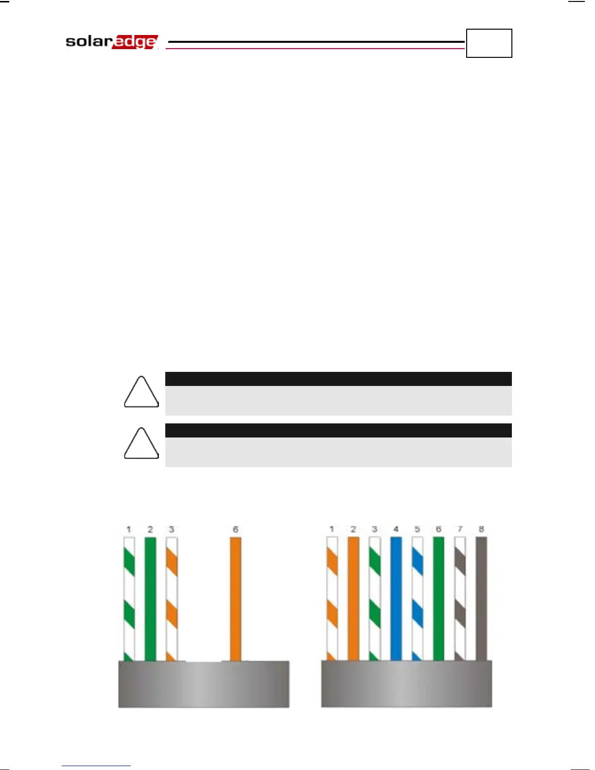
• Remove the cable’s external isolation using the crimping tool or cable
cutter and expose 8 wires. Standard cables have 8 wires (4 twisted pairs).
For Ethernet communication, 4 wires (2 twisted pairs) are used.
Figure 38: Preparing Connector Wiring