Setting Up Communication
SolarEdge Installation Guide – MAN-01-00002-1.6
72
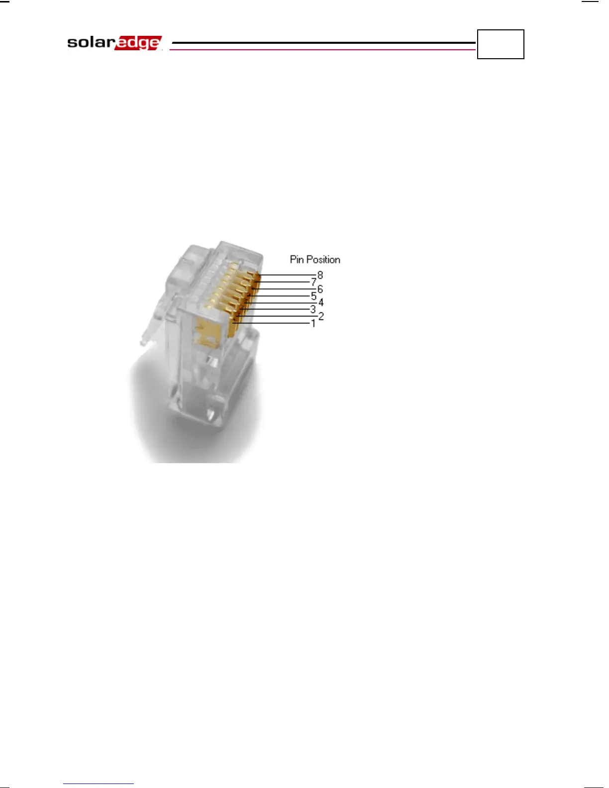
Only wires numbered 1, 2, 3 and 6 in the diagram on the left above should be
connected. To make crimping easier, wires numbered 3, 6, 7 and 8 do not
need to be connected.
5 An inverter has either RJ45/RJ11 connectors or block terminal connectors for
communication.
If the inverter has RJ45/RJ11 communication connectors, then connect as
follows:
• Insert the 4 wires into the RJ45 connector. Make sure to use pins 1, 2, 3
and 6.
Figure 39: Inserting Wires into the RJ45 Connector
• Use the Ethernet crimper to crimp the wires.
• Connect the Ethernet connector to the RJ45 plug on board in the inverter,
as shown in Figure 34.